










Ultrasonic Welding vs. Resistance Welding for Electrical Contact Assemblies and Busbars
Oct 01, 2026
Leave a message
Ultrasonic welding joins conductive metals through high-frequency mechanical vibration with limited bulk heating, while resistance welding generates a localized fusion zone through electrical current and contact resistance. For electrical contact assemblies and busbars, the selection depends on material combination, section thickness, allowable thermal exposure, required shear strength, and the electrical resistance of the finished joint.
The engineering decision is not simply "which welding process is stronger." The joint must maintain low electrical resistance, controlled mechanical strength, stable metallurgical bonding, dimensional accuracy, and repeatable production quality after stamping and assembly.
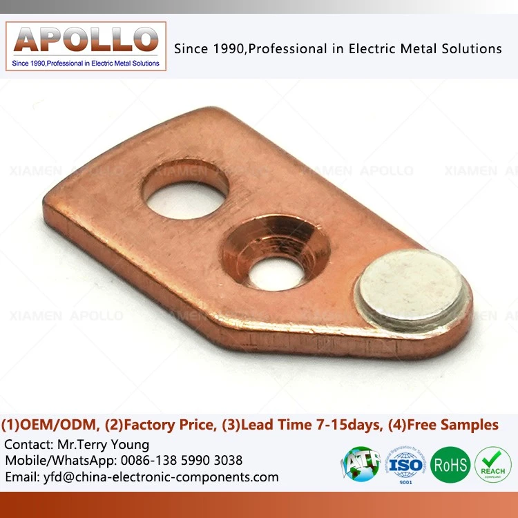
Ultrasonic Welding for AgSnO₂-Copper and Cu-Cu Connections
Low-Temperature Bonding for AgSnO₂-Cu Contact Assemblies
Ultrasonic welding is particularly applicable when the electrical contact contains a silver alloy and the substrate is copper. An ultrasonic contact welding assembly can create a solid-state bond without requiring the entire joint interface to reach the melting temperature of the base materials.
Typical applications include:
AgSnO₂-Cu contact assemblies requiring limited thermal exposure to the silver alloy.
Cu-Cu braided wire connections where strand deformation must remain controlled.
Thin copper sheets, foil stacks, terminals, and flexible conductors.
Battery and power-electronics connections where excessive heat can damage adjacent insulation.
Electrical contact bridges requiring consistent contact resistance after joining.
The welding mechanism combines controlled clamping pressure with ultrasonic vibration. Surface oxides and contaminants are disrupted at the interface, while localized plastic deformation increases the real metallic contact area.
For production qualification, the critical variables are not limited to ultrasonic frequency. Welding amplitude, weld force, energy, cycle time, material hardness, overlap area, and surface condition must be controlled as a process window.
AgSnO₂-Copper Joint Variables
| Variable | Engineering consideration | Typical quality focus |
| AgSnO₂ contact material | Silver-tin-oxide electrical contact alloy | Avoid excessive thermal degradation |
| Copper substrate | C1100 / high-conductivity copper | Maintain conductivity and dimensional stability |
| Joint thickness | Thin-sheet and layered structures | Prevent excessive deformation |
| Weld force | Determines interface pressure | Stable bonding without crushing |
| Ultrasonic amplitude | Controls interface friction and deformation | Avoid over-welding |
| Weld energy | Correlates with bonding consistency | Establish process window through DOE |
| Electrical resistance | Indicates current-path quality | 100% or sampling-based resistance verification |
| Shear force | Indicates mechanical integrity | Correlate destructive test data with weld parameters |
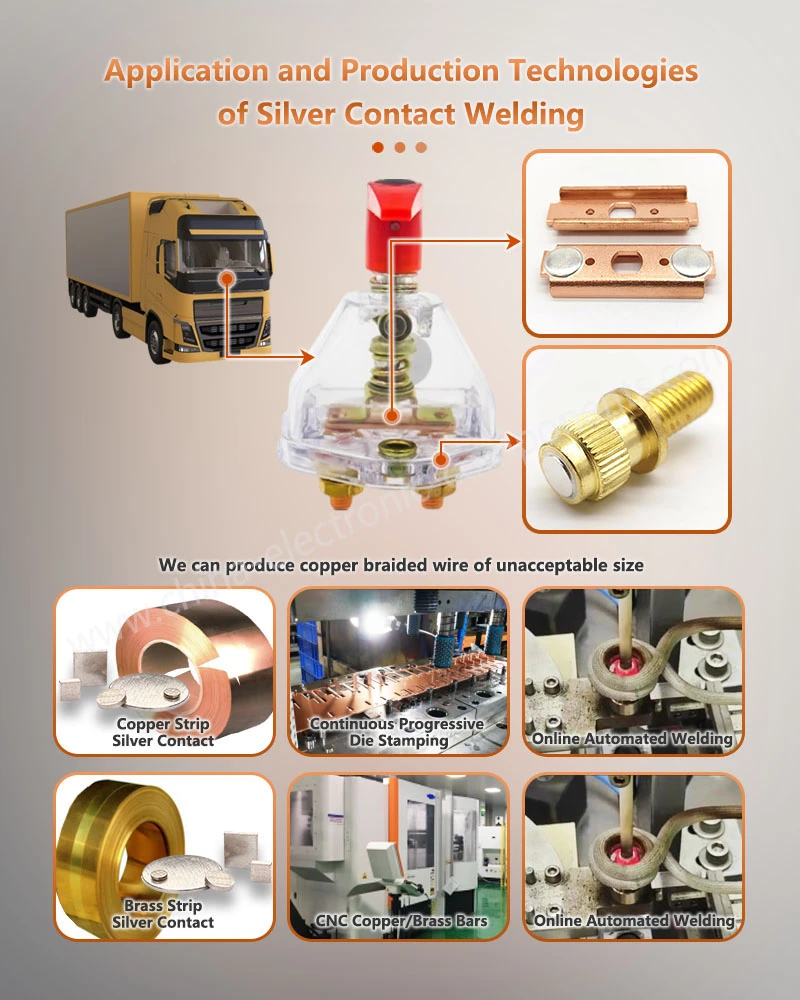
Resistance Welding for High-Strength Stamped Contact Bridges
Resistance welding uses electrical current passing through the workpieces to generate localized Joule heating. The heat generated at the interface is approximately related to:
Q = I²Rt
where I is the welding current, R is the electrical resistance, and t is the current duration.
This makes electrode force, current, weld time, material resistance, and contact geometry directly relevant to weld formation.
For thicker stamped components, resistance spot welding can generate a defined fusion zone with greater penetration than many solid-state joining processes. This makes it suitable for resistance spot welding copper contacts, stamped electrical bridges, terminals, and multilayer conductive components.
Resistance Welding of C1100 Copper Components
Copper presents a specific resistance-welding challenge because its electrical resistivity is low and its thermal conductivity is high. A large current can therefore be required to generate sufficient localized heat.
Production engineering normally focuses on:
Electrode geometry and contact area.
Electrode force stability.
Welding-current repeatability.
Current rise and fall characteristics.
Sheet thickness and stack-up.
Surface oxidation and contamination.
Electrode wear.
Nugget diameter and penetration.
Post-weld electrical resistance.
Destructive shear or peel testing.
A resistance-welded contact bridge should not be qualified only through visual inspection. Nugget formation, mechanical strength, electrical resistance, and failure mode need to be correlated with the welding process window.
Request Free DFM Evaluation & Quote
Ultrasonic vs. Resistance Welding: Material and Joint Selection
C1100 Copper vs. AgSnO₂ Contact Materials
The material combination determines whether thermal input or mechanical deformation is the dominant engineering constraint.
| Parameter | Ultrasonic Welding | Resistance Welding |
| Primary bonding mechanism | Solid-state mechanical bonding | Resistance-generated localized heating |
| Bulk material melting | Normally avoided | Fusion zone commonly formed |
| Heat-affected area | Relatively limited | More localized but higher peak temperature |
| Thin copper sheets | Highly suitable | Suitable with optimized parameters |
| Copper braid | Highly suitable | More difficult for fine-strand structures |
| Thick stamped copper | Application-dependent | Well suited |
| AgSnO₂ contact | Suitable where thermal exposure must be limited | Possible with controlled heat input |
| Weld nugget | Not the primary qualification feature | Primary weld-quality characteristic |
| Electrode requirement | Horn/anvil system | Electrodes required |
| Electrode wear | Tool wear depends on material and amplitude | Significant production variable |
| Typical validation | Shear + electrical resistance + metallography | Nugget + shear/peel + electrical resistance |
| Process optimization | Force + amplitude + energy + time | Current + force + time + electrode geometry |
Copper-to-Copper Braided Wire
Copper braid presents a different joining problem from stamped sheet metal. Individual strands have small cross-sections and oxide layers, while excessive thermal input can cause local annealing or unwanted deformation.
Ultrasonic welding can consolidate multiple copper strands against a copper terminal while retaining a relatively compact heat-affected region.
The engineering objective is to achieve:
Low electrical resistance + sufficient pull/shear strength + controlled strand consolidation.
A production specification should therefore define the acceptable electrical resistance and mechanical failure mode rather than relying solely on weld appearance.
Electrical Resistance and Shear Strength: Two Primary Acceptance Criteria
A welded electrical connection has two independent functions:
Carry current with controlled electrical loss.
Survive mechanical loading during assembly and service.
A joint can have acceptable mechanical strength while exhibiting excessive electrical resistance. Conversely, a low-resistance joint can have insufficient mechanical strength.
Electrical Resistance Measurement
Four-wire Kelvin measurement is preferred when the target resistance is sufficiently low that lead and contact resistance would otherwise affect the measurement.
The test system should control:
Test current.
Probe position.
Measurement direction.
Contact pressure.
Temperature.
Stabilization time.
Sampling frequency.
For high-current copper connections, the resistance value should be correlated with conductor geometry and effective current-carrying area rather than interpreted as an isolated number.
Shear and Pull Testing
Mechanical validation can include:
Lap-shear testing.
Pull-off testing.
Peel testing for layered structures.
Tensile testing of terminals.
Destructive cross-section analysis.
The failure mode provides additional information. A fracture through the parent material indicates a different process condition from an interfacial separation.

Process Control for IATF 16949 and PPAP Level 3 Production
IATF 16949 Process Controls for Welded Contacts
For automotive electrical contact components, welding should be treated as a controlled special process rather than an isolated assembly operation.
A production control plan can include:
Incoming material verification.
CMM dimensional inspection.
Stamping-process monitoring.
Weld parameter monitoring.
Electrode or horn condition checks.
Electrical resistance testing.
Shear-force validation.
Metallographic inspection.
Traceability by batch or production lot.
MSA and gauge R&R.
SPC for critical dimensions and weld characteristics.
For PPAP Level 3 submission, the supplier may need to establish a documented relationship between DFMEA → PFMEA → Control Plan → Work Instructions → inspection records → capability studies → validation results.
CMM Inspection and ±0.01 mm Dimensional Control
The welded assembly must retain dimensional compatibility with the downstream contactor, relay, fuse, switchgear, or busbar assembly.
Depending on the product geometry, critical dimensions may include:
Contact-center position.
Hole diameter.
Terminal flatness.
Weld location.
Contact height.
Bend angle.
Overall length.
Copper sheet thickness.
For precision stamped components, selected dimensions may be controlled to ±0.01 mm, subject to the actual product drawing and functional tolerance stack-up.
Welded Contact Bridge Supplier Selection: Qualification Matrix
A welded contact bridge supplier should be evaluated against the complete manufacturing chain rather than welding capability alone.
| Qualification Item | Recommended Verification |
| Raw material | Material certificate and composition verification |
| Stamping | Dimensional inspection and tool-process records |
| Welding | Parameter window and process validation |
| Electrical performance | Low-resistance measurement |
| Mechanical performance | Shear / tensile / peel testing |
| Metallurgy | Cross-section and microscopic inspection |
| Dimensional accuracy | CMM inspection |
| Traceability | Lot-level production records |
| Automotive quality | IATF 16949 system |
| Submission package | PPAP Level 3 capability |
| Environmental compliance | RoHS / REACH documentation |
| Process capability | SPC / Cp / Cpk where specified |
A supplier capable of stamping but unable to correlate weld parameters with resistance and mechanical results creates additional qualification work for the buyer. The preferred sourcing model is one where stamping, joining, inspection, traceability, and PPAP documentation are managed within one controlled manufacturing system.
When to Select Ultrasonic or Resistance Welding
Ultrasonic Welding: Thin Copper, Braid and Low Thermal Exposure
Select ultrasonic welding when the design requires:
Copper braid consolidation.
Thin conductive sheets.
Limited bulk heating.
Solid-state joining.
AgSnO₂-to-copper contact joining.
Compact electrical connection zones.
Controlled deformation of thin conductive materials.
Resistance Welding: Thick Stamped Components and Defined Weld Nuggets
Select resistance welding when the design requires:
Thick stamped copper components.
High localized heat input.
Defined fusion nuggets.
High production throughput.
Repeatable electrode positioning.
Structural joining of stamped contact bridges.
The final process decision should be based on material stack-up, thickness, joint geometry, electrical resistance target, mechanical-load requirement, thermal sensitivity, and production volume.
Download Contact Assembly Design Specification
Production Validation: Resistance, Shear and Metallographic Evidence
A qualified electrical contact assembly should have three complementary forms of evidence.
Electrical Validation
Measure the completed current path and establish the acceptable resistance range under defined test conditions.
For low-resistance copper joints, the measurement method itself becomes part of the specification.
Mechanical Validation
Shear or tensile testing establishes whether the joint can withstand assembly forces, vibration, thermal cycling, and service loads.
The acceptance criterion should specify both the minimum force and the acceptable failure mode.
Metallographic Validation
Cross-sectional analysis can identify:
Incomplete bonding.
Voids.
Cracks.
Excessive deformation.
Insufficient weld penetration.
Excessive heat-affected regions.
Irregular nugget geometry.
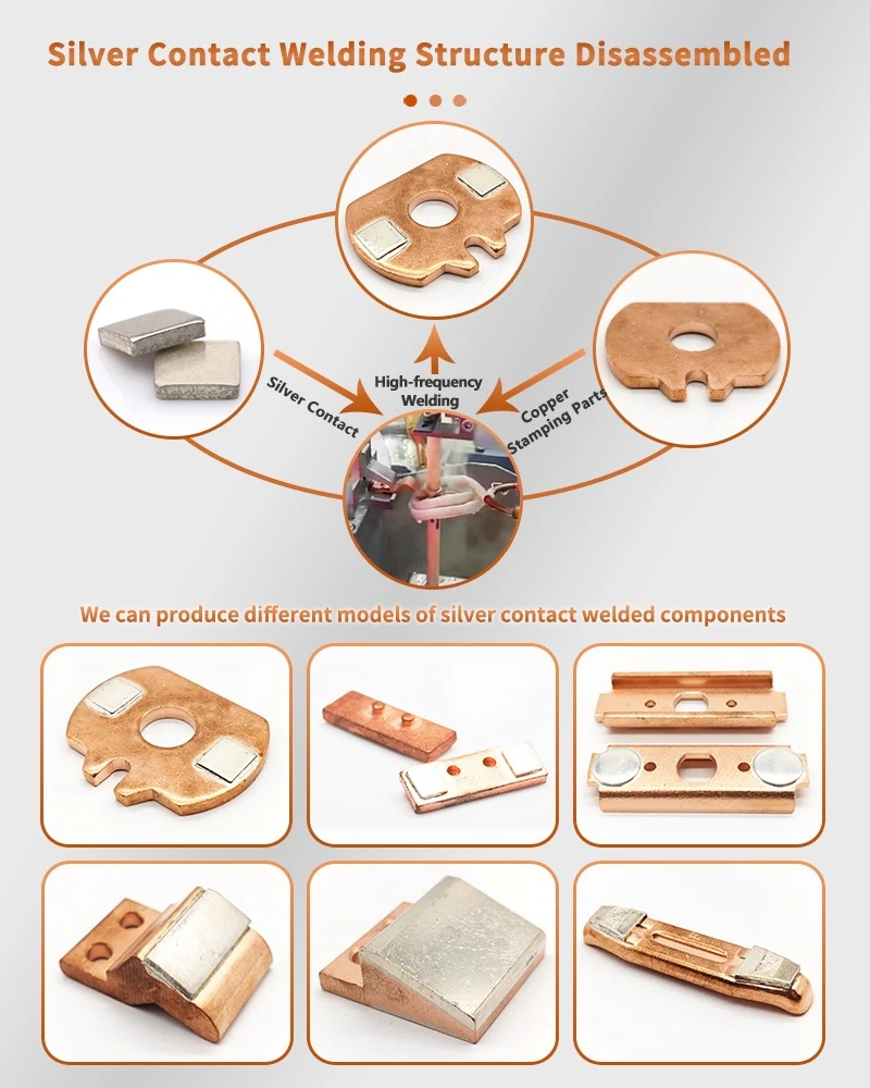
Engineering Specification Checklist for Electrical Contact Welding
Before releasing a welded contact assembly for mass production, the engineering drawing and supplier specification should define:
Material: C1100, C2680, AgSnO₂, or specified silver alloy.
Material thickness: Actual sheet or conductor thickness.
Joint configuration: Lap, butt, overlap, braid-to-terminal, or contact-to-carrier.
Welding process: Ultrasonic or resistance welding.
Electrical requirement: Maximum allowable joint resistance.
Mechanical requirement: Minimum shear or tensile force.
Dimensional requirement: Critical dimensions and tolerance, such as ±0.01 mm where applicable.
Surface condition: Plating, oxidation, contamination, and cleaning requirements.
Inspection method: Kelvin resistance measurement, CMM, metallography and destructive testing.
Quality system: IATF 16949 where automotive supply requirements apply.
Submission: PPAP Level 3 where specified by the customer.
Environmental compliance: RoHS and REACH requirements.
FAQ: Electrical Contact Welding Procurement
What is the typical PPAP Level 3 documentation required for welded contact assemblies?
PPAP Level 3 normally requires the applicable design records, process flow, PFMEA, control plan, dimensional results, material and performance test results, MSA evidence, process capability data, sample parts, and PSW, subject to the customer's specific submission requirements.
How do I choose ultrasonic welding for copper braid instead of resistance welding?
Ultrasonic welding is generally considered when copper braid requires strand consolidation with limited bulk heating. Resistance welding is more suitable when the joint requires a defined fusion zone in thicker stamped components.
How is electrical resistance tested on a welded copper contact?
A four-wire Kelvin measurement method is commonly used for low-resistance joints. The test specification should define current, probe location, temperature, stabilization conditions, sampling frequency, and maximum allowable joint resistance.
contact us

Send Inquiry