



High-Precision Contact Assemblies for Thermostats and Thermal Overload Protectors
Nov 11, 2026
Leave a message
Thermostat and thermal overload protector performance depends on the interaction between bimetal disc movement, contact geometry, contact force, and electrical joint integrity. A contact assembly must maintain repeatable switching temperature, stable contact resistance, and sufficient opening clearance while preventing contact welding under the specified electrical load. For OEM production, silver-alloy contact selection, precision riveting or resistance spot welding, and 100% optical inspection provide measurable control over contact position, profile, and assembly consistency.
Switching Reliability: Contact Geometry and Bimetal Disc Response
A thermostat typically uses a bimetal element that changes curvature in response to temperature. When the temperature reaches its operating threshold, the disc snaps between two stable or semi-stable positions, changing the electrical contact state.
The contact assembly directly affects the switching interface. Contact height, alignment, surface profile, and attachment strength influence the final contact force and separation distance.
How contact geometry affects thermostat switching
The contact interface must accommodate the movement characteristics of the bimetal disc without introducing excessive mechanical resistance or unstable electrical engagement.
Three geometric parameters are particularly important:
Contact height: Determines the initial contact position and influences the bimetal disc's installed deflection.
Contact face profile: Controls the effective contact area and local pressure distribution.
Contact center position: Determines whether the moving and fixed contacts engage concentrically or with an intentional offset.
A contact that is too high may increase the installed preload and shift the switching characteristics. A contact that is too low may reduce contact force, resulting in unstable electrical engagement or increased resistance.
The acceptable dimensions must therefore be derived from the thermostat's mechanical stack-up and calibrated switching-temperature requirements.
Electrical contact welding and mechanical sticking
Contact welding occurs when localized electrical heating creates a metallic bond between opposing contact surfaces. The risk depends on current, voltage, load type, contact material, contact force, surface condition, and arc duration.
Inductive loads can be particularly demanding because stored magnetic energy may sustain an arc during interruption. Motor windings, solenoids and transformer-related loads may therefore impose different contact requirements from resistive heaters.
Contact sticking can also result from excessive mechanical preload, surface deformation, or insufficient opening clearance.
| Failure condition | Possible cause | Functional consequence | Recommended control |
| Contact welding | Excessive arc energy or unsuitable contact alloy | Contacts remain electrically closed | Load-specific switching endurance test |
| High contact resistance | Contamination, low contact force, or poor joint integrity | Localized heating | Four-wire resistance measurement |
| Contact bounce | Incorrect contact geometry or inadequate mechanical damping | Repeated electrical transitions | Dynamic switching evaluation |
| Contact misalignment | Riveting or welding position deviation | Reduced effective contact area | Optical position measurement |
| Insufficient opening gap | Incorrect contact height or bimetal installation | Failure to interrupt current | Gap measurement at specified temperature |
| Contact detachment | Weak riveted or welded joint | Loss of electrical continuity | Pull-off or shear testing |
Millisecond-scale switching and response-time considerations
Thermostat switching response is governed primarily by the thermal response of the bimetal element, its geometry, heat transfer conditions, and mechanical snap action. The contact assembly must not introduce additional mechanical interference that delays or prevents the intended movement.
A distinction should be made between:
Thermal response time: Time required for the sensing element to reach its switching condition.
Mechanical switching time: Time required for the bimetal element to move between contact states.
Electrical interruption time: Time associated with contact separation and the extinction of the electrical arc.
These parameters require different test methods. A contact supplier should not claim a universal millisecond switching response based only on contact geometry.
Flat, Spherical and Crown Contact Profiles for Different Switching Loads
Contact face geometry influences the initial contact area, local pressure, surface wear and current distribution. Selecting a profile requires consideration of contact force, material hardness, switching current, and the expected number of operating cycles.
Flat contact profiles for controlled positioning
Flat contact faces provide a relatively broad nominal contact area when two surfaces are correctly aligned.
Typical characteristics include:
Relatively simple contact geometry.
Straightforward dimensional inspection.
Dependence on surface flatness and parallelism.
Sensitivity to angular misalignment between mating contacts.
Flat profiles can be suitable for thermostat designs where the contact support and bimetal movement provide controlled alignment.
The actual electrical contact area remains smaller than the apparent geometric area because microscopic surface asperities carry the current.
Spherical contact profiles for localized engagement
Spherical or domed contact faces create an initial contact region around a smaller central area. This geometry can accommodate certain alignment variations and concentrate contact pressure.
Potential engineering effects include:
Higher local contact pressure under the same applied force.
Reduced sensitivity to minor angular mismatch in selected designs.
Different wear and deformation behavior compared with flat contacts.
Increased local stress at the contact interface.
The profile radius must be controlled because excessive curvature can produce high local pressure, while insufficient curvature may reduce the intended alignment benefit.
Crown contact profiles for controlled multi-point engagement
Crown-shaped contact faces use a defined raised profile to establish a controlled contact region. Depending on the design, the crown may provide a central contact point or a distributed engagement pattern.
The geometry must be evaluated against the mating contact profile. A crown that is too high can cause excessive local stress, while an incorrect crown diameter may change the contact force distribution.
Contact profile comparison matrix
| Design factor | Flat contact | Spherical contact | Crown contact |
| Nominal geometry | Planar | Domed or radiused | Raised crown profile |
| Initial engagement | Broad nominal face | Localized central region | Defined raised region |
| Alignment tolerance | Depends on flatness and parallelism | Can accommodate selected angular variations | Depends on crown and mating geometry |
| Local contact pressure | Distributed according to actual surface condition | Concentrated near the apex | Concentrated around designed raised features |
| Wear behavior | Depends on face flatness and material | Depends on radius and contact force | Depends on crown height and profile |
| Inspection priority | Flatness, diameter, and position | Radius, height, and concentricity | Crown height, profile, and symmetry |
| Design consideration | Surface parallelism | Local stress and deformation | Profile consistency and mating geometry |
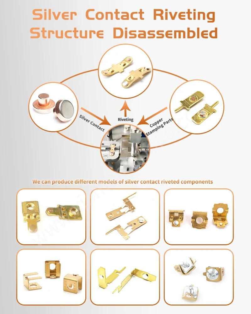
Silver contact material selection for thermal switching applications
The contact alloy should be selected according to the switching load, contact force, arc exposure, temperature range, and required operating life.
| Contact material | General characteristics | Engineering considerations |
| Pure silver (Ag) | High electrical and thermal conductivity | Suitable for applications requiring high conductivity; switching resistance to welding must be evaluated |
| Silver-nickel (AgNi) | Silver-based alloy with improved resistance to material transfer in selected switching applications | Alloy composition and contact force influence switching performance |
| Silver-tin oxide (AgSnO₂) | Metal-oxide contact material used in selected switching applications | Contact resistance, manufacturing method, and arc behavior require application-specific validation |
| Silver-graphite (AgC) | Used in selected switching applications requiring different arc and wear characteristics | Mechanical strength and contact resistance must be evaluated |
The material selection should not be based on silver content alone. The required contact performance depends on the electrical load profile and the complete switching system.
Request Silver Contact Material Evaluation
Contact-to-Bimetal Joining: Precision Riveting and Resistance Spot Welding
The connection between the contact element and the bimetal disc must withstand repeated snap action, thermal cycling, and electrical loading without loosening or changing the contact position.
Two common joining approaches are mechanical riveting and resistance spot welding. Their suitability depends on bimetal composition, contact material, component thickness, and design requirements.
Precision riveting of silver contacts onto bimetal discs
Riveting mechanically locks the contact element to the bimetal support through controlled deformation of a rivet shank or contact base.
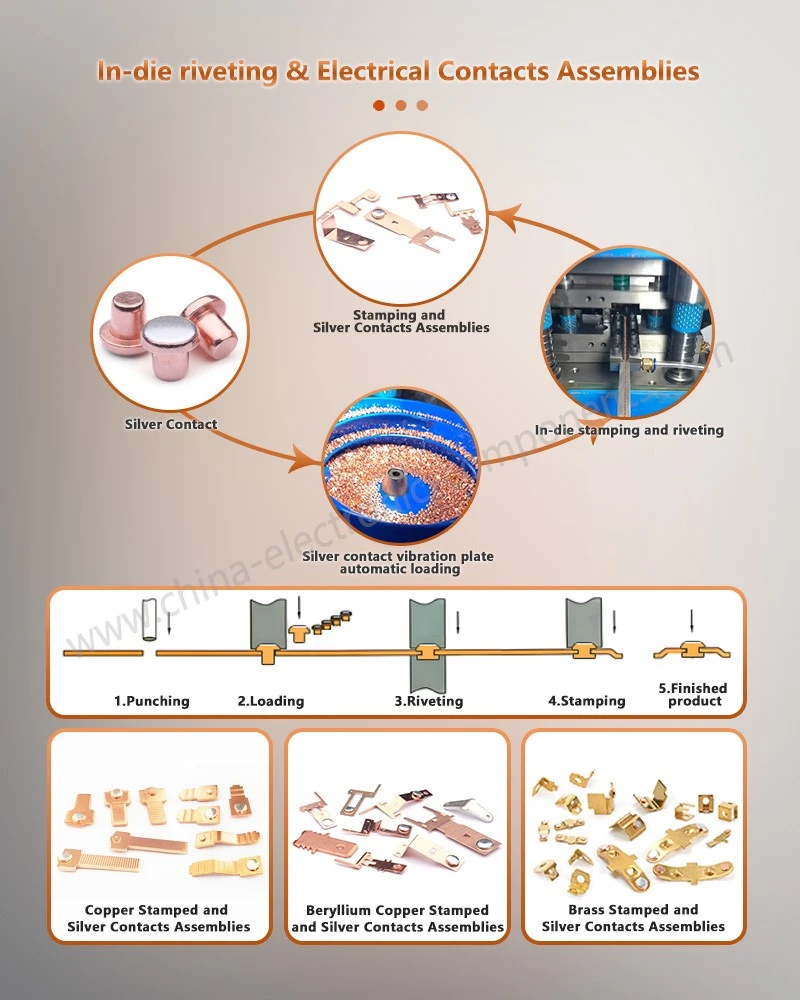
A typical process sequence includes:
1. Bimetal disc positioning and datum alignment.
2. Receiving-hole inspection or preparation.
3. Silver contact feeding and orientation.
4. Contact-to-disc alignment.
5. Controlled riveting and upsetting.
6. Contact-height and profile inspection.
7. Mechanical retention testing.
Key process variables include rivet length, hole diameter, material thickness, punch travel, riveting force, and final upset geometry.
Excessive riveting force may distort the bimetal disc or alter its free-state curvature. Insufficient deformation may lead to weak retention or contact movement during thermal cycling.
Resistance spot welding for contact attachment
Resistance spot welding generates localized heat at the interface through electrical resistance while electrodes apply pressure.
For thermostat contact assemblies, the process must account for the electrical and thermal properties of both the contact material and bimetal substrate.
Important variables include:
Welding current.
Pulse duration.
Electrode force.
Electrode tip diameter and condition.
Contact positioning.
Surface cleanliness.
Cooling and electrode maintenance.
Bimetal discs may contain different metallic layers with different thermal expansion and electrical properties. Excessive welding energy can affect the local structure or distort the disc.
Welding schedules should therefore be established through material-specific process trials and verified using destructive testing and dimensional inspection.
Riveting versus resistance spot welding for bimetal assemblies
| Engineering factor | Precision riveting | Resistance spot welding |
| Joining principle | Mechanical deformation | Localized electrical heating |
| Thermal influence | No welding heat input | Localized heat-affected region |
| Material compatibility | Requires suitable mechanical engagement | Requires compatible electrical and thermal welding behavior |
| Bimetal distortion risk | Related to clamping and upsetting force | Related to heat input and electrode force |
| Main process variables | Hole size, rivet length, punch travel, force | Current, time, electrode force, tip geometry |
| Main failure modes | Loose joint, cracked rivet, disc deformation | Weak weld, expulsion, interface separation, thermal distortion |
| Typical validation | Pull-off, shear, dimensional inspection | Weld shear, metallographic sectioning, dimensional inspection |
| Production integration | Progressive die or automated riveting | Automated welding station |
The two processes should be compared using the finished thermostat's mechanical and electrical acceptance criteria rather than equipment cycle time alone.
Bimetal disc protection during joining
The bimetal disc is a functional sensing and actuation component. Its free-state curvature and thermal switching characteristics must be protected during contact attachment.
Recommended controls include:
Support the disc close to the joining region without constraining its functional curvature.
Control clamping force and punch contact position.
Avoid excessive local deformation around the contact attachment point.
Verify disc flatness or free-state profile before and after joining.
Check switching temperature and reset behavior after process validation.
Use dedicated fixtures that prevent incorrect disc orientation.
Contact Height, Opening Gap, and Dimensional Stack-Up Control
Contact height and opening gap are closely related to thermostat switching behavior. Small dimensional changes can affect installed preload, contact force, opening clearance, and the final mechanical position of the bimetal disc.
A contact assembly supplier should therefore control the dimensions that directly influence the thermostat's functional stack-up.
Contact height measurement
Contact height is measured relative to a specified reference surface or datum on the bimetal disc or contact carrier.
Measurement should distinguish between:
Free-state contact height before installation.
Contact height after riveting or welding.
Installed contact height within the thermostat assembly.
Contact position under specified temperature or mechanical conditions.
The measurement fixture must avoid applying excessive force to the bimetal disc, as this can change its apparent profile.
Opening gap and contact separation
The opening gap is the distance between opposing contact faces when the thermostat is in the open state under a specified condition.
The gap affects dielectric clearance and the ability to interrupt the specified electrical load. However, a larger gap does not automatically guarantee better interruption performance because arc behavior also depends on voltage, current, load inductance, contact material, and opening speed.
The gap specification should identify:
Temperature condition.
Mechanical state of the bimetal disc.
Measurement datum.
Contact face reference points.
Measurement force, if applicable.
Minimum and maximum acceptance limits.
Dimensional stack-up analysis
The final contact position is determined by several dimensions across the component and assembly.
| Stack-up contributor | Dimensional influence | Recommended control |
| Bimetal disc thickness | Affects component position and stiffness | Incoming material inspection |
| Free-state disc curvature | Influences initial contact position | Profile measurement |
| Rivet or contact base height | Determines attachment geometry | Supplier dimensional inspection |
| Upset height | Influences final contact position | Riveting process monitoring |
| Contact face profile | Determines actual engagement geometry | Optical profile measurement |
| Support or housing datum | Establishes installed reference position | Fixture and CMM verification |
| Assembly preload | Changes operating contact position | Functional assembly testing |
Tolerance allocation should be performed across the full mechanical stack-up. Assigning tight tolerances to individual parts without checking the assembled condition may increase manufacturing cost without improving switching consistency.
Request Thermostat Contact Assembly DFM Review
100% Optical Inspection and Automated Dimensional Screening
For high-volume thermostat contact production, manual sampling alone may not detect every contact-position or surface-profile defect. Automated optical inspection can verify selected geometric characteristics on every component or at a defined production inspection point.
The inspection system should be designed around the critical-to-quality characteristics rather than relying on a generic visual pass/fail algorithm.
Machine vision inspection of contact geometry
A calibrated optical inspection system can measure or detect:
Contact presence and orientation.
Contact center position.
Contact diameter.
Contact face profile.
Contact height, where the optical setup supports reliable height measurement.
Rivet-head geometry.
Visible cracks, contamination, and surface damage.
Bimetal disc orientation and profile features.
For three-dimensional characteristics, telecentric imaging, laser displacement sensors, or optical profilometry may be more appropriate than a conventional two-dimensional camera.
Optical inspection versus manual inspection
| Inspection factor | Manual inspection | Automated optical inspection |
| Contact presence | Operator-dependent | Camera-based detection |
| Contact center position | Gauge or visual comparison | Calibrated image measurement |
| Contact diameter | Optical comparator or gauge | Automated edge detection |
| Surface defects | Depends on magnification and operator | Programmed defect detection |
| Contact height | Requires a dedicated gauge | Laser or 3D optical measurement |
| Production speed | Limited by inspection labor | Suitable for inline screening |
| Data recording | Often manual | Can store measured results and defect images |
| Main limitation | Operator variation and sampling coverage | Calibration, lighting, algorithm, and false-rejection control |
Automated optical inspection is not a substitute for mechanical or electrical testing. It detects observable geometric and surface defects but cannot independently confirm pull-off strength, weld integrity, or contact resistance.
Measurement system validation and GR&R
Before optical inspection is used as a production acceptance method, the measurement system should be validated.
Key activities include:
Confirming calibration against traceable reference standards.
Establishing repeatability and reproducibility.
Verifying measurement stability across shifts.
Evaluating sensitivity to lighting, focus, and part orientation.
Establishing false-accept and false-reject performance.
Defining inspection limits and escalation rules.
For customer-controlled automotive production, Measurement System Analysis (MSA) and Gauge Repeatability and Reproducibility (GR&R) should follow the applicable customer requirements and approved methodology.
A 100% inspection claim should specify which characteristics are inspected, the inspection location, the measurement method, and the rejection logic.

Functional Validation: Contact Resistance, Thermal Cycling and Switching Endurance
Dimensional conformity establishes whether the contact assembly matches the drawing. Functional testing determines whether it performs under the operating conditions of the thermostat or thermal overload protector.
The test program should reflect the end-device specification and the intended electrical load.
Contact resistance measurement
Four-wire Kelvin measurement is commonly used for low-resistance electrical connections. It reduces the effect of test-lead resistance by separating the current path from the voltage-sensing path.
The test specification should define:
Measurement current.
Voltage-sensing points.
Contact condition and applied force.
Ambient or stabilized temperature.
Measurement sequence.
Instrument accuracy and calibration.
Initial and post-endurance acceptance limits.
The test fixture must reproduce the intended electrical interface as closely as possible.
Thermal cycling and contact stability
Thermostat contact assemblies experience repeated heating and cooling. These cycles can influence joint retention, surface condition, and dimensional stability.
A suitable validation plan may include:
| Test | Objective | Main evaluation |
| Thermal cycling | Assess dimensional and joint stability | Contact position and attachment integrity |
| Switching endurance | Assess performance over repeated operations | Contact welding, erosion, and resistance change |
| Temperature-rise test | Evaluate heating under specified current | Contact and terminal temperature |
| Contact resistance after cycling | Detect electrical degradation | Resistance change |
| Mechanical retention after cycling | Verify attachment stability | Pull-off or shear force |
| Switching temperature verification | Confirm thermostat functional behavior | Operating and reset temperatures |
Test temperature, dwell time, cycle count, and electrical load must be specified by the end-device design. They should not be replaced with generic values that may not represent the actual application.
Preventing contact welding through material and load matching
Contact welding risk is influenced by the complete switching condition. A contact alloy that performs well under resistive loading may behave differently under inductive or capacitive loading.
Engineering review should consider:
Rated voltage and current.
Inrush current.
Load power factor or inductance.
Switching frequency.
Contact opening speed.
Contact force and opening gap.
Arc duration and interruption conditions.
Ambient temperature and enclosure design.
For motor protection, compressor systems, and thermal overload devices, the electrical load profile should be included in contact material selection and endurance validation.
IATF 16949 Quality Documentation for Thermostat Contact Assembly Suppliers
Thermostat contact assemblies used in automotive and electrical protection systems require traceable control of materials, joining operations and functional characteristics.
The supplier quality system should connect material specifications, process parameters, inspection results and final functional testing.
Recommended quality control plan
| Process stage | Critical characteristic | Inspection method | Quality record |
| Silver contact incoming inspection | Alloy and dimensions | Material certificate and dimensional inspection | Incoming inspection report |
| Bimetal incoming inspection | Grade, thickness and curvature | Certificate and profile measurement | Material batch record |
| Contact forming | Diameter and face profile | Optical measurement | Process inspection record |
| Riveting | Upset height and retention | Dimensional and pull-off test | Riveting validation report |
| Resistance welding | Weld strength and interface integrity | Shear test and metallography | Welding validation report |
| Contact positioning | Center location and height | Optical or 3D measurement | Dimensional inspection report |
| Final assembly | Opening gap and alignment | Gap gauge or optical measurement | Final inspection report |
| Functional validation | Resistance and switching behavior | Electrical and thermal testing | Functional test report |
PFMEA and process risk controls
A process FMEA should identify potential failures at each manufacturing stage.
Examples include:
Incorrect silver contact alloy.
Bimetal disc mixed between material grades.
Contact misorientation during feeding.
Excessive riveting force.
Insufficient weld energy.
Contact height outside specification.
Bimetal curvature altered during joining.
Optical inspection calibration drift.
Incorrect opening-gap measurement.
Inadequate traceability between material batches and finished components.
The Control Plan should specify the inspection method, frequency, sample size, responsible function and reaction plan for each critical characteristic.
PPAP and production approval
Where the customer requires PPAP, the submission package should reflect the actual production process and approved component revision.
Typical documentation may include:
Approved engineering drawings.
Material and performance specifications.
Process flow diagram.
PFMEA and Control Plan.
Dimensional inspection results.
Material test reports.
Riveting or welding validation records.
Contact resistance and functional test results.
MSA and capability studies, where required.
Appearance approval or customer-specific records.
PPAP Level 3 requirements should be confirmed with the customer before submission. Documentation must correspond to the actual manufacturing site and production tooling intended for mass production.
FAQ: Thermostat Contact Assembly Manufacturing
1. Which silver contact material is suitable for thermostat and thermal overload protector assemblies?
Pure silver, AgNi, and AgSnO₂ are possible options, depending on rated current, load type, contact force, arc exposure, and service-life requirements. Final selection requires application-specific switching validation.
2. How can manufacturers prevent bimetal disc deformation during contact riveting?
Use a dedicated support fixture, controlled punch travel, and defined riveting force. Inspect free-state curvature and contact height before and after joining to verify that the bimetal disc retains its specified geometry.
3. Can 100% optical inspection verify thermostat contact assembly quality?
It can screen defined visual and dimensional characteristics, including contact presence, position, diameter, and selected height measurements. Mechanical retention, weld integrity, contact resistance, and switching performance require separate validation tests.
contact us

Send Inquiry