



Expanding Applications for New Energy Fuses: Circuit Protection in Electric Vehicles and Photovoltaic Systems, and an Analysis of Ceramic Insulating Structures
Nov 10, 2026
Leave a message
With the rapid development of new energy vehicles, photovoltaic (PV) power generation, and energy storage systems, electrical systems in the new energy sector are evolving toward higher voltages, higher currents, greater power density, and increased integration. Compared to traditional low-voltage power distribution environments, the DC circuits found in new energy equipment are characterized by higher voltage levels, complex fault-current dynamics, and the persistence of DC arcs-all of which impose more stringent requirements on the breaking capacity, insulation performance, and long-term operational stability of overcurrent protection components.
As a fundamental component in electrical protection systems, a fuse functions by having its internal element melt under abnormal current conditions, thereby interrupting the faulty circuit and limiting damage to batteries, power electronic devices, and electrical connections caused by short-circuit currents. In high-voltage DC applications, a fuse must not only possess a breaking capacity matched to the system voltage and prospective short-circuit current, but it must also feature robust insulation, heat resistance, and mechanical reliability.
Evolving Protection Requirements for Fuses in New Energy Systems
The electrical architecture of new energy equipment typically encompasses multiple voltage levels and circuits with diverse load characteristics. Electric vehicles, for instance, involve traction batteries, high-voltage auxiliary systems, and low-voltage control systems; PV systems comprise components such as module strings, DC combiners, inverters, and AC grid-connection interfaces. Because fault-current characteristics vary by location, fuses must be configured in a tiered manner based on specific circuit parameters.
During actual operation, new energy equipment may be subject to factors such as inrush currents, load switching, ambient temperature fluctuations, and anomalies in electrical connections. Fuses must remain stable under normal operating currents and permissible short-duration surge currents, while also triggering promptly when fault currents exceed the defined protection curve. Selection should be based on a comprehensive assessment of rated voltage, rated current, breaking capacity, time-current characteristics, ambient temperature, and installation conditions-relying solely on the equipment's rated power is insufficient for determining the appropriate fuse specifications.
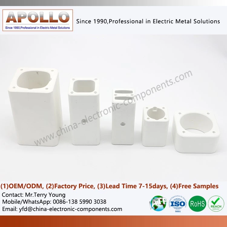
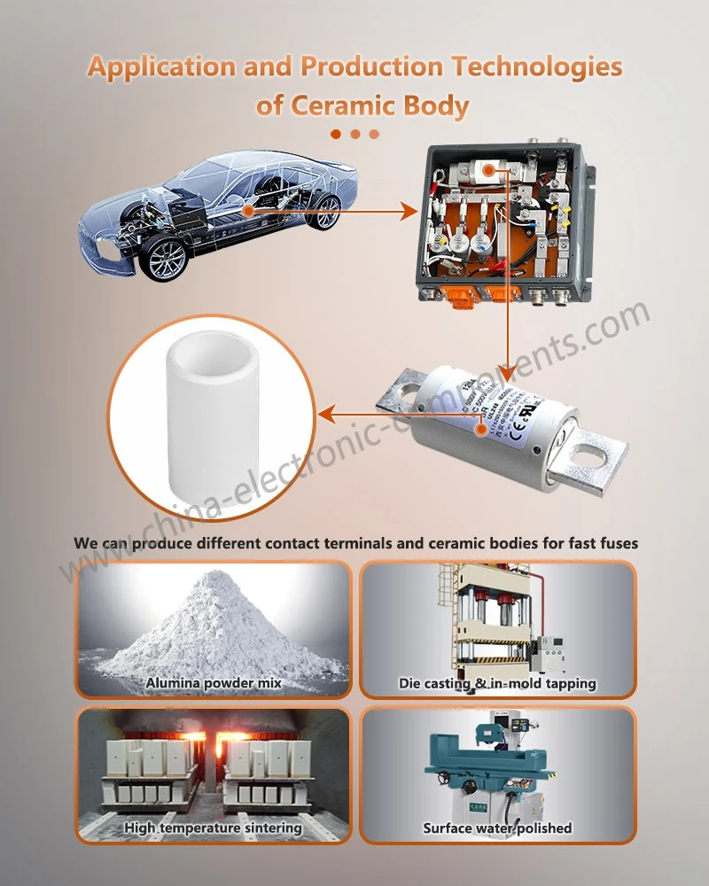
For high-voltage DC fuses, the absence of the periodic zero-crossing points found in AC systems makes extinguishing an arc after a fault occurs significantly more challenging. Consequently, the internal structure of the fuse, the arc-extinguishing filler material, the insulating housing, and the design of the terminal connections all play critical roles in determining its actual breaking performance. Some products utilize alumina (aluminum oxide) ceramics as the material for their insulating housings to ensure structural stability and electrical insulation in high-temperature environments.
Configuration and Application of Fuses in Electric Vehicles
The high-voltage power system and low-voltage auxiliary system of an electric vehicle (EV) serve distinct power supply functions. As the voltage platforms of traction batteries rise, and the integration of electric drive systems, thermal management systems, and on-board charging systems increases, it becomes necessary to establish a multi-layered overcurrent protection system that covers both the main circuit and various functional branch circuits.
1. Protection of the Traction Battery Main Circuit
The traction battery serves as the primary energy source for an electric vehicle. A high-voltage DC fuse is typically installed at the output of the battery pack to protect against external short circuits and other faults that could lead to severe overcurrent. The fuse is connected in series within the main battery circuit; when a fault current reaches the fuse's operating threshold, the internal element melts-interrupting the current and reducing the risk of the battery continuing to discharge energy into the fault location.
The main circuit of a traction battery imposes rigorous requirements on fuses. The components must be compatible with the battery system's maximum operating voltage, prospective short-circuit current, and load characteristics, while also being capable of withstanding the vibrations, temperature fluctuations, and space constraints inherent in vehicle operation. For products utilizing ceramic insulation, the term "ceramic for DC automotive fuses" is often used; the housing material and internal architecture must align with the fuse's rated parameters and interruption requirements.
The ceramic housing of a fuse serves not only as an external insulator but must also endure the high temperatures and pressure changes that occur during the fusing process. "Insulating electrical steatite ceramic" is one type of material used for fuse housings; however, the specific material selection should always be determined based on the product design, operating temperature, and electrical performance requirements.
2. Protection of High-Voltage Auxiliary Equipment Branch Circuits
The high-voltage system of an electric vehicle typically encompasses various components, such as drive motor controllers, air-conditioning compressors, PTC heaters, on-board chargers, and DC-DC converters. Because these loads differ in terms of operating current, startup characteristics, and failure modes, it is generally necessary to configure appropriate branch circuit protection components tailored to the specific system architecture.
When a short circuit or severe overcurrent occurs in a high-voltage auxiliary component, a branch-circuit fuse can-in accordance with its designed protective characteristics-interrupt the faulty circuit, thereby minimizing the impact of the fault on other high-voltage components. Such applications impose specific requirements regarding the fuse's physical dimensions, terminal connection methods, mounting orientation, and insulation clearances.
In terms of product construction, the term "ceramic casing for fuse link" refers to the ceramic housing of a fuse element. For high-voltage electric vehicle (EV) applications, an "alumina ceramic tube for high-voltage EV fuses" specifically highlights the use of alumina (aluminum oxide) ceramic tubing. Alumina ceramics offer excellent electrical insulation, heat resistance, and mechanical strength, making them well-suited for fuse structures that must withstand high thermal loads; however, the ultimate performance depends on factors such as the ceramic formulation, sintering process, dimensional precision, and overall design.
3. Low-Voltage Auxiliary Circuit Protection
In addition to high-voltage power systems, electric vehicles are equipped with 12V or other low-voltage power circuits that supply electricity to body controllers, lighting, in-vehicle infotainment systems, sensors, and auxiliary actuators. Fuses in these low-voltage circuits are primarily used to protect wiring harnesses and electronic equipment, preventing overheating or component damage caused by short circuits or overloads.
High-voltage and low-voltage fuses differ significantly in terms of rated voltage, breaking capacity, and structural design; they are not interchangeable.
For high-voltage DC applications, an "alumina ceramic tube for electrical automotive fuses" serves as a descriptive term for the ceramic component, while an "Al2O3 alumina ceramic tube for high-voltage fuses" emphasizes the application of alumina material within the insulation structure of a high-voltage fuse.
Fuse Configuration and Application in Photovoltaic (PV) Systems
The output power of a photovoltaic (PV) power generation system is influenced by factors such as solar irradiance, module temperature, and operating conditions. Multiple PV modules are connected in series to form a "string," which is then routed through a combiner unit to an inverter. Because PV arrays typically utilize a DC power architecture, reverse currents can occur between strings. Consequently, protection design on the DC side must specifically account for scenarios such as string short circuits, module failures, and anomalies within the combiner circuitry.
1. Protection for Photovoltaic (PV) String Circuits
In certain PV array designs, multiple strings operate in parallel. If a short circuit or other anomaly occurs in one string, the other, properly functioning strings may feed reverse current into the faulty branch. Should this current exceed the limits specified for the PV modules and wiring, it could lead to localized overheating of the modules or damage to connection components.
Consequently-provided it aligns with system design requirements and applicable standards-DC fuses can be installed within PV string circuits to mitigate the risk of reverse overcurrent. The fuse's rated voltage must exceed the maximum open-circuit voltage that the PV array could reach at its lowest operating temperature. Meanwhile, its rated current and protection characteristics must be determined based on the maximum series fuse rating of the PV modules, the short-circuit current of the strings, and the overall system configuration.
In such applications, an "alumina ceramic insulator tube for fuses" refers to the ceramic component used within the fuse assembly. For PV and new-energy electrical equipment that must withstand high DC voltages, the insulation properties, heat resistance, and dimensional consistency of the ceramic tube are critical to the overall reliability of the fuse structure.
2. Protection for DC Combiner Stages
The output currents from PV strings are gathered into a DC combiner box before being transmitted to the inverter. The combiner stage typically encompasses multiple string inputs, a DC busbar, disconnect switches, and protective components. Given the high number of connection points and an operating environment often exposed to outdoor factors-such as temperature fluctuations, humidity, and dust-robust protection is essential.
Depending on the system design, DC fuses can be positioned at the string inputs or other critical points to limit the impact of fault currents on the combiner equipment and downstream power electronics. It is important to note that fuse configuration must be determined based on system topology, module parameters, and relevant standards; simply adding a single master output fuse is not necessarily appropriate for every combiner circuit.
For high-voltage DC applications, components such as "alumina ceramic tubes for high-voltage automotive fuses" or "alumina ceramic tubes for high-voltage EV fuses" illustrate the specific role that alumina ceramic tubes play in the construction of high-voltage fuses. When selecting components, it is essential to verify that the product meets the specific requirements for voltage rating, breaking capacity, and environmental adaptability of the corresponding photovoltaic (PV) DC circuit; the product's scope of application cannot be determined solely by its name.
3. Protection for Inverters and the AC Grid-Connection Side
PV inverters are responsible for converting the DC electricity generated by PV modules into AC electricity that meets grid-connection standards.
Because the DC input side, power conversion unit, and AC output side of an inverter exhibit distinct electrical characteristics, protection schemes must be tailored to the specific type of circuit.
On the AC grid-connection side, protection components must be configured based on the AC system voltage, short-circuit current, and power distribution architecture. Since AC and DC fuses differ in their arc-extinguishing mechanisms and operational conditions, DC fuses should not be used in AC protection applications without prior validation, nor should AC fuses be used in high-voltage DC circuits.
Materials and Manufacturing Requirements for Ceramic Tubes in High-Voltage Fuses
With the advancement of high-voltage platforms for electric vehicles (EVs) and new energy power equipment, the material properties of the internal insulating structures of fuses have garnered increased attention. Ceramic tubes, which typically serve as the external insulating housing or critical insulating components of a fuse, must provide a balance of electrical insulation, heat resistance, mechanical strength, and dimensional stability-all within a constrained space.
Alumina ceramic is a common insulating material used in high-voltage fuses. Depending on specific product design requirements, various alumina content levels and formulations can be employed to achieve the necessary dielectric, thermal, and mechanical properties. A "95% Alumina Ceramic Tube for High-Voltage Fuses" refers to a ceramic tube based on a 95% alumina material system; its specific performance metrics must be confirmed through material testing and finished-product validation.
In the context of high-voltage fuses for electric vehicles, terms such as "insulated ceramic tube in EV fuses" or "ceramic tube for EV DC fuses" are used to describe the insulating ceramic components found within these devices. Depending on the applicable standards and product specifications, this may also encompass components such as "ceramic tubes for EV British Standard (BS) fuses" or similar series-based products. Such products must be designed in accordance with relevant standards, dimensional drawings, end-structure specifications, and assembly requirements; relying solely on a series name is insufficient for technical validation.
Furthermore, with the development of charging equipment and infrastructure for new energy vehicles (NEVs), the fuses used in such equipment must be configured based on factors including input power source, power rating, and protection architecture. The term "ceramic tube for EV charger fuse link" refers to the ceramic component within an EV charging fuse; its application requires careful consideration of the device's operating voltage, load characteristics, heat dissipation conditions, and insulation requirements.
From a manufacturing perspective, quality control for fuse ceramic tubes typically encompasses raw material composition, molding density, sintering temperature, dimensional tolerances, surface defects, and electrical performance. The quality of the ceramic tube's inner surface and end structures directly affects the assembly and operational integrity of the internal fuse components. For high-voltage products, the entire fuse assembly must undergo rigorous testing-including insulation, temperature rise, breaking capacity, and durability-to ensure optimal structural compatibility between the ceramic component, the fuse element, the filler material, and the end caps.

Key Technical Assessment for Procuring Fuses for New Energy Applications
Selecting fuses for new energy applications requires more than just considering rated current and physical dimensions; it necessitates an evaluation based on system protection coordination. First, the application scenario and circuit type must be clearly defined-for instance, whether the fuse is intended for a traction battery main circuit, high-voltage auxiliary equipment, a photovoltaic string, a DC combiner, or an AC grid-connection point.
Second, it is essential to specify the system's maximum operating voltage, normal operating current, prospective short-circuit current, load surge characteristics, and ambient temperature range to determine the appropriate fuse ratings and time-current characteristics.
For ceramic structural components, specific attention should be paid to the material type, alumina content, tube length, inner and outer diameters, wall thickness, end-structure geometry, dimensional tolerances, and surface quality. If the product is intended for use with specific fuse elements, end caps, or filler materials, it is also necessary to evaluate assembly clearances, differences in thermal expansion, and overall structural compatibility.
During bulk procurement, it is recommended to incorporate material testing, dimensional inspection, visual checks, and verification of critical electrical performance into the quality control process. For high-voltage DC fuses, the material properties of the ceramic tube alone do not fully represent the protective capability of the complete fuse; this must ultimately be verified through design validation of the entire unit and testing against applicable standards.
As the sectors for new energy vehicles, photovoltaic power generation, and charging infrastructure continue to evolve, fuses-along with their ceramic insulating components-are trending toward higher voltage compatibility, miniaturization, greater structural precision, and stable, large-scale manufacturing. For engineering procurement projects with custom requirements, it is advisable to provide product drawings, ceramic material specifications, critical dimensional tolerances, intended application scenarios, and the specifications of the associated fuses during the inquiry phase.
This facilitates proper material selection, structural assessment, and sample validation. Such early-stage engineering verification helps effectively manage the risk of potential mismatches between the ceramic tube and the overall fuse structure, establishing a reliable foundation for final product definition and volume procurement.
contact us
Send Inquiry