



Insulation Coating Solutions for High-Voltage Copper Busbars and Stamped Components
Nov 09, 2026
Leave a message
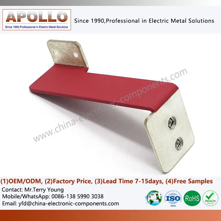
High-voltage copper busbars installed in compact distribution cabinets require electrical insulation to control phase-to-phase clearance, prevent accidental contact, and reduce the risk of arc faults. Epoxy powder coating, PVC hot-dip coating, and heat-shrink tubing provide different combinations of dielectric performance, coating thickness, mechanical protection, and geometric coverage. Selection must be based on operating voltage, insulation coordination, conductor geometry, thermal conditions and applicable fire-safety requirements-not coating material alone.
Electrical Insulation Requirements for Compact High-Voltage Busbars
Copper busbars carry high current between circuit breakers, contactors, inverters, battery systems, and distribution terminals. In compact electrical enclosures, the available installation space may restrict the distance between energized conductors and grounded metal structures.
Insulation coating provides a dielectric barrier over selected conductive surfaces. It can reduce the risk of unintended electrical contact and help manage insulation requirements where air clearance and creepage distance are constrained.
However, a coated busbar must still comply with the insulation coordination requirements of the complete electrical assembly. Coating does not automatically replace the required clearance, creepage distance, or protective enclosure design.
Arc flashover and insulation failure mechanisms
Several failure mechanisms should be considered when specifying an insulated copper busbar:
Phase-to-phase flashover: Electrical discharge between adjacent conductors when the insulation system cannot withstand the applied electric field.
Phase-to-ground breakdown: Failure of insulation between an energized busbar and a grounded cabinet structure.
Surface tracking: Formation of a conductive path along an insulating surface under electrical stress and contamination.
Partial discharge: Localized electrical discharge in voids, interfaces, or regions of concentrated electric field.
Thermal degradation: Changes in dielectric properties caused by sustained temperature exposure or localized overheating.
Mechanical damage: Cracking, abrasion, or coating removal during bending, installation, or maintenance.
Environmental deterioration: Moisture, chemical exposure, or contamination affecting insulation resistance and surface integrity.
The insulation system must be evaluated under the actual service conditions. A coating that passes a short-duration dielectric test may still be unsuitable if it develops cracks during busbar bending or loses adhesion after thermal cycling.
Insulation design parameters for copper busbars
| Design parameter | Engineering significance | Verification method |
| Operating voltage | Defines the electrical stress experienced by the insulation system | System specification |
| Rated insulation voltage | Establishes the insulation design basis | Applicable equipment standard |
| Dielectric withstand voltage | Evaluates resistance to electrical breakdown | AC or DC withstand test |
| Coating thickness | Influences dielectric performance and dimensional fit | Coating thickness gauge or cross-section |
| Creepage distance | Controls surface leakage path | Drawing inspection |
| Air clearance | Controls the shortest path through air | Dimensional inspection |
| Thermal class | Defines the permitted temperature exposure | Material datasheet and thermal testing |
| Adhesion | Determines coating retention during handling and service | Specified adhesion test |
| Flame performance | Evaluates material response to ignition and flame exposure | Applicable UL 94 classification |
The required dielectric withstand voltage must be established from the equipment's rated voltage, insulation coordination, overvoltage category, and applicable product standard. A generic dielectric-strength value in kV/mm cannot replace system-level qualification.
Standards used in high-voltage insulation design
The following standards may be relevant depending on the application and target market:
| Standard | Scope | Application relevance |
| IEC 60664-1 | Insulation coordination for low-voltage supply systems | Clearance, creepage and solid insulation |
| IEC 61439 series | Low-voltage switchgear and controlgear assemblies | Electrical assembly verification |
| IEC 60947 series | Low-voltage switchgear and controlgear | Device insulation and electrical performance |
| UL 94 | Flammability of plastic materials | Material flame classification |
| IEC 60243 series | Electric strength of insulating materials | Dielectric strength testing |
| IEC 60216 series | Thermal endurance properties of electrical insulating materials | Thermal aging evaluation |
| IEC 60068 series | Environmental testing | Temperature, humidity, and environmental exposure |
UL 94 V-0 is a material flammability classification under specified test conditions. It does not establish dielectric withstand voltage, tracking resistance, or the fire performance of the complete electrical assembly.
Epoxy Powder Coating vs. PVC Hot-Dip Coating vs. Heat-Shrink Tubing
The three main insulation approaches differ in application method, coating structure, and suitability for complex busbar geometry.
For a copper busbar with multiple bends, punched holes, threaded features, or connection terminals, coating coverage must be considered together with dimensional tolerances and electrical contact requirements.
Epoxy powder coating for rigid copper busbars
Epoxy powder coating applies electrically insulating thermosetting powder to a prepared conductive surface. The powder is deposited through an electrostatic process or fluidized-bed process, followed by controlled curing.
For fluidized-bed epoxy coating, a preheated copper busbar is immersed in a suspended powder bed. Powder particles adhere to the heated surface and melt to form a continuous coating. The component may then undergo additional curing according to the powder manufacturer's process specification.
Typical process stages include:
1. Degreasing and removal of surface contaminants.
2. Surface preparation and drying.
3. Preheating to the specified process temperature.
4. Powder application through fluidized-bed immersion or another approved method.
5. Coating thickness adjustment.
6. Thermal curing according to the material specification.
7. Cooling and dimensional inspection.
8. Dielectric and coating-quality verification.
Epoxy powder coating is frequently considered for rigid busbars used in switchgear, power distribution cabinets, and electrical control assemblies.
Its suitability depends on the powder formulation, copper surface condition, component geometry, and curing profile.
PVC hot-dip coating for shaped conductors
PVC hot-dip coating applies a polymer insulation layer to a prepared metal component through controlled immersion in a heated PVC coating system.
The coating process must control immersion time, material temperature, withdrawal speed, and cooling conditions. These variables influence coating thickness, surface finish, and coverage around edges and bends.
PVC insulation may be suitable for busbars and stamped components where flexibility, impact resistance and the specified temperature range are important.
However, PVC formulations vary considerably. Their dielectric properties, thermal performance, flame classification, and chemical resistance must be verified against the selected compound's technical data.
Heat-shrink tubing for localized insulation
Heat-shrink tubing is a preformed polymer sleeve that contracts when heated. It is installed over the copper busbar and shrinks to conform to the component profile.
It is commonly used for straight sections, selected bends, and localized insulation areas. Tubing with an adhesive inner layer may provide additional sealing, depending on the product construction.
Important design considerations include:
Initial and recovered internal diameter.
Shrink ratio.
Recovered wall thickness.
Minimum bending radius.
Operating temperature range.
Dielectric rating.
Flame classification.
Compatibility with the busbar surface and installation process.
Heat-shrink tubing can be difficult to apply consistently around complex three-dimensional shapes, sharp transitions, or multiple terminal branches. Its use must account for installation access and the possibility of trapped air or incomplete recovery.
Technical comparison of three insulation methods
| Engineering factor | Epoxy powder coating | PVC hot-dip coating | Heat-shrink tubing |
| Insulation structure | Cured thermoset coating | Polymer coating layer | Preformed polymer sleeve |
| Application method | Electrostatic or fluidized-bed deposition | Heated immersion process | Sleeve installation and thermal recovery |
| Geometry suitability | Suitable for many rigid and complex profiles, subject to coverage validation | Suitable for selected shaped components | Best suited to accessible profiles and sections |
| Coating continuity | Depends on surface preparation and powder coverage | Depends on immersion and withdrawal control | Depends on sleeve fit and recovery |
| Thickness control | Controlled through powder, temperature and process conditions | Controlled through compound and immersion parameters | Determined mainly by tubing specification |
| Mechanical protection | Depends on coating formulation and thickness | Depends on PVC compound and thickness | Depends on sleeve wall thickness and polymer type |
| Thermal performance | Depends on epoxy formulation and curing | Depends on PVC compound | Depends on tubing polymer |
| Repairability | Local repair may require an approved coating process | Repair depends on compound and application method | Damaged sleeve sections may be replaceable |
| Dimensional impact | Adds coating thickness to external dimensions | Adds polymer thickness | Adds recovered sleeve wall thickness |
| Typical application | Rigid switchgear busbars and stamped conductors | Selected shaped busbars and electrical parts | Terminal sections, cable transitions and localized insulation |
No single coating method is suitable for every copper busbar. The selection should be based on the required dielectric performance, geometry, operating temperature, and assembly tolerances.
Request Busbar Insulation DFM Evaluation
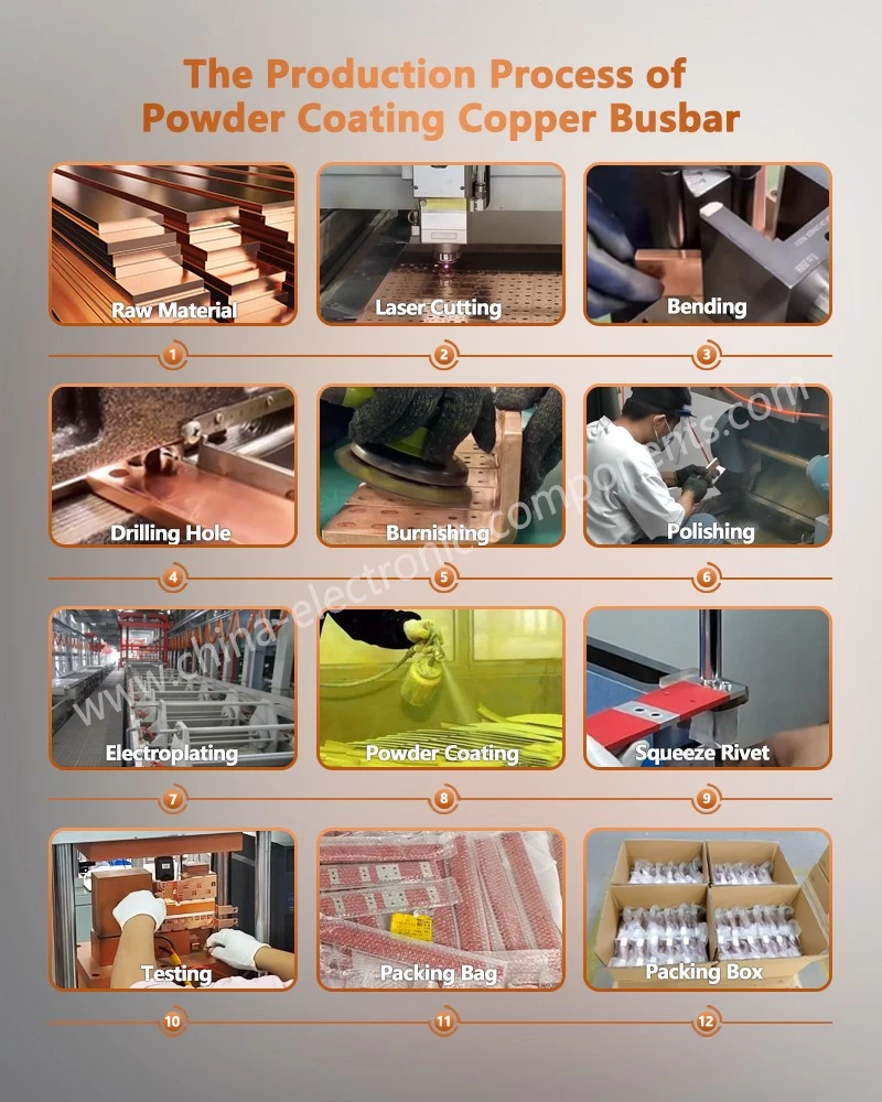
Dielectric Withstand, Coating Thickness and UL 94 V-0 Requirements
A coating specification should define measurable electrical, dimensional, and material requirements. Specifying only a coating name or nominal thickness is insufficient for production approval.
The required insulation performance depends on the electrical system, material construction, and test conditions.
Dielectric strength versus dielectric withstand voltage
These two parameters describe different properties.
Dielectric strength is generally expressed as electric field strength, such as kV/mm, under a specified material test method and specimen configuration.
Dielectric withstand voltage is a test voltage applied to a component or assembly for a defined duration and under specified conditions. The result depends on more than the coating material's intrinsic dielectric strength.
Factors affecting the withstand performance of a coated busbar include:
Coating thickness and uniformity.
Surface contamination and pretreatment.
Voids, pinholes, and exposed edges.
Busbar geometry and electric-field concentration.
Test electrode arrangement.
Voltage waveform and frequency.
Temperature and humidity.
Coating damage caused by handling or assembly.
A coating with a high laboratory dielectric-strength value may still fail a component-level withstand test if a sharp edge, pinhole or insufficiently coated region creates a local field concentration.
Coating thickness and coverage inspection
Thickness should be specified according to the selected insulation material and the electrical design.
For epoxy powder coating, thickness measurement may use a suitable non-destructive coating gauge calibrated for the copper substrate and coating system. Cross-section measurement can be used for process validation or investigation.
For PVC coating, thickness should be evaluated at representative locations, including corners, bends, and edges.
For heat-shrink tubing, recovered wall thickness should be checked against the tubing specification.
| Inspection location | Potential issue | Recommended verification |
| Flat busbar surface | Uneven coating build | Multiple-point thickness measurement |
| Sharp edges | Thin coverage or exposed copper | Visual inspection and cross-section |
| Bend radius | Cracking or coating thinning | Post-bend inspection |
| Punched holes | Powder accumulation or incomplete coverage | Visual and dimensional inspection |
| Threaded areas | Coating intrusion into threads | Thread gauge and masking inspection |
| Terminal contact surfaces | Unwanted insulation coverage | Masking and contact-surface inspection |
| Overlapping or narrow gaps | Incomplete coating penetration | Visual inspection and process validation |
UL 94 V-0 and flame-performance verification
UL 94 classifies the flammability behavior of plastic materials under defined specimen dimensions and test conditions.
For V-0 classification, the tested material must meet specified afterflame and related criteria. The classification applies to the tested material formulation and specimen thickness.
It does not mean that a complete coated busbar assembly is fireproof or that it automatically meets every electrical equipment fire-safety requirement.
When specifying UL 94 V-0, procurement and engineering teams should verify:
Exact coating or tubing material formulation.
Certified or documented material classification.
Tested specimen thickness.
Material supplier and product identification.
Applicability of the classification to the supplied coating system.
Any additional customer-specific flame or smoke requirements.
For railway electrical equipment, for example, EN 45545 may apply to the relevant fire-protection requirements. Its applicability and specific requirement set must be established from the vehicle and component classification.
Thermal aging and insulation durability
Copper busbars experience Joule heating during current conduction. The coating must retain its required electrical and mechanical properties at the expected operating temperature.
Thermal evaluation should consider:
Continuous operating temperature.
Short-duration temperature peaks.
Temperature cycling.
Heat transfer from adjacent terminals and components.
Localized heating at bolted joints.
Thermal aging of the coating material.
IEC 60216 provides a framework for evaluating the thermal endurance of electrical insulating materials. The material's thermal index should not be interpreted as a guaranteed operating temperature for every coated busbar assembly.
Recommended insulation quality validation matrix
| Characteristic | Test or inspection | Acceptance basis |
| Coating thickness | Calibrated coating gauge or cross-section | Approved drawing and coating specification |
| Dielectric withstand | AC or DC hipot test | Customer-defined voltage and duration |
| Insulation resistance | Insulation resistance measurement | Product specification |
| Adhesion | Approved coating adhesion test | Material specification |
| Surface integrity | Visual inspection | No unacceptable cracks, pinholes or exposed copper |
| Flame classification | UL 94 material documentation | Required classification and tested thickness |
| Thermal endurance | Thermal aging or cycling | Application-specific acceptance criteria |
| Dimensional fit | CMM or dimensional gauges | Assembly drawing tolerances |
Request Insulation Specification Review
Copper Surface Preparation and Epoxy Powder Coating Process Control
Coating quality begins before powder application. Oil, oxide, dust, and surface irregularities can reduce adhesion or cause coating defects.
Copper busbars may undergo stamping, bending, punching, deburring, and cleaning before insulation. The surface condition after these operations directly affects coating consistency.
Surface preparation before coating
A typical preparation route may include:
1. Removal of stamping oil and grease.
2. Cleaning of metallic particles and loose contaminants.
3. Controlled surface treatment where specified.
4. Rinsing or neutralization where required by the selected chemistry.
5. Drying and moisture removal.
6. Inspection before coating.
The selected pretreatment must be compatible with copper and the powder coating system. Aggressive chemical treatment or uncontrolled mechanical abrasion may change surface condition and affect dimensional or electrical requirements.
Epoxy powder coating process variables
| Process variable | Effect on coating | Control approach |
| Surface cleanliness | Influences adhesion and defect formation | Cleaning verification |
| Copper preheat temperature | Influences powder melting and deposition | Calibrated temperature monitoring |
| Powder condition | Affects fluidization and application consistency | Material storage and batch control |
| Immersion time | Influences coating build | Validated process window |
| Powder particle condition | Influences surface finish and deposition | Supplier specification and process monitoring |
| Curing temperature | Influences crosslinking and final properties | Part-temperature monitoring |
| Cooling conditions | Influences handling and dimensional stability | Controlled cooling procedure |
For fluidized-bed coating, the busbar temperature before immersion is particularly important. If the component is too cold, powder may not melt and fuse adequately. Excessive preheat may cause excessive coating build, poor surface finish, or thermal damage to sensitive component features.
The curing schedule should follow the coating manufacturer's technical data and be validated using actual component temperature rather than oven-air temperature alone.
Masking and contact-surface protection
Busbars commonly include areas that must remain electrically conductive, such as:
Bolted connection pads.
Contact interfaces.
Threaded holes.
Grounding points.
Weld locations.
Terminal interfaces.
These areas require controlled masking before coating. Poor masking can cause coating contamination on electrical contact surfaces, while excessive masking can leave exposed copper in regions that require insulation.
A masking plan should be linked to the component drawing and identify both coated and uncoated surfaces.
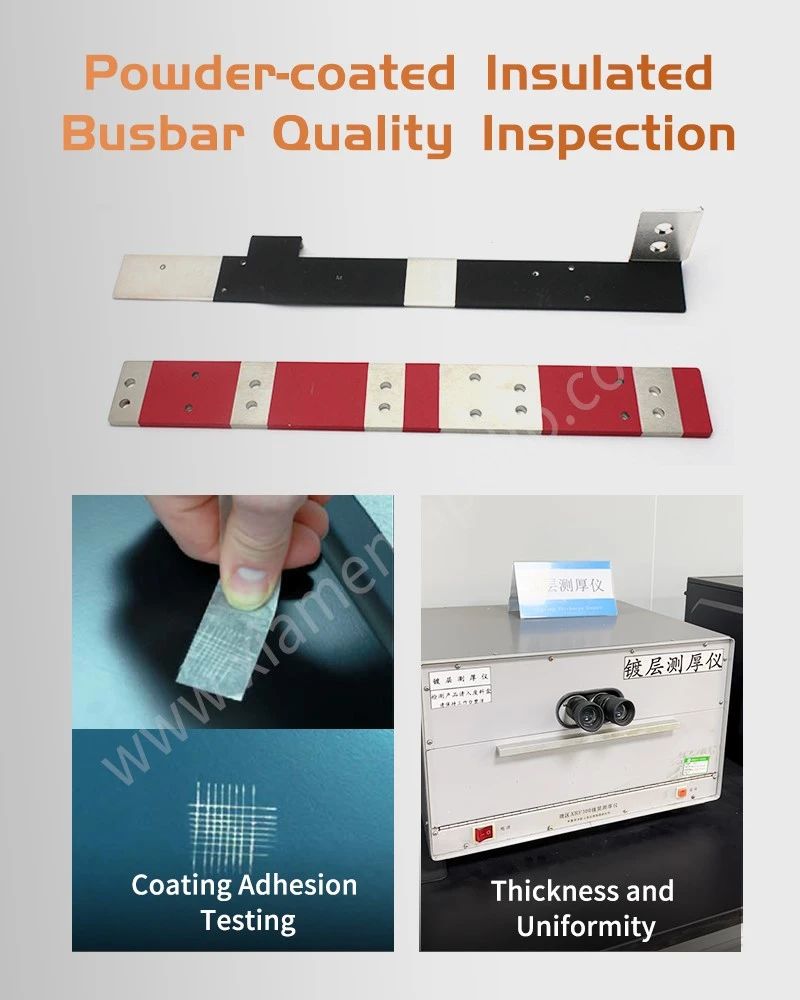
Integrated Copper Busbar Stamping and Insulation Manufacturing
Combining precision stamping and insulation coating within one manufacturing workflow can reduce handling between suppliers and improve control over the relationship between component geometry and coating coverage.
The process sequence should be defined around the final busbar drawing, material specification, and electrical requirements.
Integrated manufacturing sequence
A typical production route for an insulated copper busbar may include:
| Production stage | Process | Main quality characteristic |
| 1 | Copper material inspection | Grade, thickness and conductivity documentation |
| 2 | Blanking and piercing | Hole position, outline and burr condition |
| 3 | Bending and forming | Bend angle, radius and flatness |
| 4 | Joining, if required | Weld or brazed joint integrity |
| 5 | Deburring and cleaning | Edge condition and surface cleanliness |
| 6 | Masking | Protection of conductive interfaces |
| 7 | Epoxy or PVC insulation application | Coverage and coating thickness |
| 8 | Curing or cooling | Material-specific process condition |
| 9 | Dimensional inspection | Terminal position and assembly fit |
| 10 | Electrical insulation testing | Dielectric withstand and insulation resistance |
| 11 | Final inspection and packing | Surface condition and handling protection |
The actual sequence may change depending on whether coating is applied before or after certain joining operations. For example, welding after coating may damage the insulation and require a defined rework or recoating procedure.
Copper material selection: C1100 vs. C2680
Copper busbars are commonly manufactured from high-conductivity copper grades. C1100 is a widely used oxygen-free or electrolytic tough-pitch copper designation depending on the applicable material standard and specification. C2680 is a copper-zinc brass alloy and has different conductivity and mechanical characteristics.
| Property | C1100 copper | C2680 brass |
| Material family | High-copper alloy | Copper-zinc alloy |
| Electrical conductivity | High | Significantly lower than C1100 |
| Formability | Suitable for many busbar forming operations | Suitable for selected stamped electrical parts |
| Strength | Depends on temper and processing | Depends on temper and processing |
| Typical use | High-current busbars and conductive components | Terminals, connectors and selected stamped hardware |
| Coating considerations | Surface preparation and oxide control | Alloy-specific pretreatment and adhesion validation |
For high-current busbars, C1100 is generally preferred where electrical conductivity is the dominant requirement. C2680 may be appropriate for smaller stamped terminals or mechanical components where its combination of strength and formability meets the design requirements.
The actual conductivity value should be taken from the specified material standard and temper. A nominal grade designation alone is insufficient for a procurement specification.
Post-coating dimensional control
Insulation adds material to the external dimensions of a busbar. This can affect terminal spacing, bolt access, insertion into supports, and clearance between adjacent conductors.
Dimensional inspection should focus on:
Overall busbar envelope.
Hole diameter and thread accessibility.
Terminal pad dimensions.
Bend angle and formed profile.
Coating thickness at narrow gaps.
Fit within insulating supports.
Clearance to adjacent conductive parts.
CMM inspection may be used for complex three-dimensional busbar geometries, while coating thickness gauges and dedicated fixtures support routine production checks.
Electrical validation after forming and coating
A busbar may pass dielectric testing before bending but develop coating cracks during subsequent forming or assembly. Therefore, the inspection sequence should reflect the actual manufacturing route.
For components coated after forming, validation should focus on coating coverage and dielectric integrity in the final geometry.
For components requiring post-coating assembly operations, additional inspection may be needed after installation or mechanical handling.
The final test plan should identify whether dielectric withstand testing is performed on individual components or the complete electrical assembly.
Design and Procurement Checklist for Insulated Copper Busbar OEM Projects
An effective RFQ package should include sufficient information for the coating supplier to assess material, geometry, insulation, and inspection requirements.
Technical inputs required for an insulation coating quotation
| Required input | Example information | Why it matters |
| Copper grade | C1100 or specified equivalent | Determines conductivity and forming response |
| Material temper | Drawing-defined temper | Affects bending and surface condition |
| Busbar thickness | Drawing dimension | Determines mechanical and dimensional design |
| Component geometry | 2D drawing and 3D CAD | Defines coating access and masking |
| Operating voltage | System rated voltage | Establishes insulation design basis |
| Dielectric test requirement | Voltage, duration, and waveform | Defines electrical validation |
| Coating type | Epoxy, PVC, or heat-shrink | Determines material and process route |
| Coating thickness | Approved range | Controls insulation and dimensional build |
| Flame requirement | UL 94 classification, where applicable | Defines material selection |
| Operating temperature | Continuous and peak conditions | Determines thermal suitability |
| Uncoated areas | Terminal pads, holes, and interfaces | Defines masking requirements |
| Annual volume | Forecast quantity | Supports process and tooling planning |
| Quality documentation | Inspection plan, PPAP scope, and material records | Defines production release requirements |
Common design issues identified during DFM
| Design issue | Potential production impact | Recommended design review |
| Sharp external edges | Thin coating or local breakdown risk | Review edge radius and deburring |
| Narrow gaps | Incomplete coating coverage | Check powder or liquid access |
| Deep recesses | Uneven deposition | Review coating method and orientation |
| Small threaded holes | Coating intrusion | Define masking or post-process treatment |
| Tight terminal tolerances | Assembly interference after coating | Include coating build-in dimensional stack-up |
| Complex bend geometry | Coating cracking or thinning | Validate forming and coating sequence |
| Large uncoated contact areas | Masking variation | Define masking dimensions and inspection points |
FAQ: Insulated Copper Busbar Coating and Electrical Insulation
1. Which insulation coating is suitable for high-voltage copper busbars in compact distribution cabinets?
Epoxy powder coating is commonly considered for rigid copper busbars requiring continuous surface coverage. PVC coating and heat-shrink tubing may suit other geometries. Selection depends on voltage, temperature, coating thickness, and assembly requirements.
2. Does UL 94 V-0 certification guarantee that an insulated copper busbar meets high-voltage dielectric requirements?
No. UL 94 V-0 evaluates material flammability under specified conditions. Dielectric withstand, insulation resistance, creepage, and clearance require separate verification against the applicable electrical equipment specification.
3. Can copper busbar stamping and insulation coating be completed by one OEM supplier?
Yes, where the supplier has the required stamping, forming, surface preparation, coating, and inspection capabilities. The manufacturing route should define masking, coating thickness, dimensional checks, and final dielectric testing.
contact us
Send Inquiry