



Heavy-Duty DC Contactor Components for Rail Transit and Renewable Energy Systems
Sep 19, 2026
Leave a message
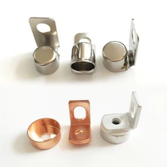
Heavy-duty DC contactor components for rail transit and renewable energy systems must withstand high-voltage arc erosion, mechanical vibration, and repeated thermal cycling. Copper-tungsten (CuW) and silver tungsten carbide (AgWC) contact materials combined with vacuum brazing technology provide stable electrical switching performance for high-current DC applications.
For rail transit DC contactor assemblies, the key engineering targets are low contact resistance, high arc erosion resistance, and structural reliability under vibration environments. Apollo Electronic Components (Xiamen) Co., Ltd manufactures high-current copper contacts, brazed contact assemblies, and precision metal components with IATF 16949 quality control systems, CMM inspection, and PPAP Level 3 documentation.

DC Contactor Challenges Under Rail Transit Conditions: 1000V DC, High Vibration, and Arc Energy Control
Rail transit DC contactors operate under conditions significantly different from conventional low-voltage relays. During train acceleration, braking, and power conversion cycles, the contact system experiences high current switching, electromagnetic forces, mechanical shock, and arc plasma erosion.
Typical engineering requirements include:
DC voltage range: 750V DC / 1500V DC / 3000V DC traction systems
Continuous current: 200A–1000A+ depending on application
Mechanical vibration compliance: IEC 61373 railway vibration testing
Electrical endurance: >100,000 switching cycles depending on load profile
Contact resistance stability: <50μΩ after endurance testing
The main failure modes of heavy-duty DC contactors include:
| Failure Mode | Root Cause | Engineering Countermeasure |
| Contact welding | Excessive arc energy and thermal load | CuW / AgWC contact material selection |
| Contact erosion | High-temperature plasma during DC interruption | High-melting-point tungsten alloy contacts |
| Increased resistance | Oxidation and surface degradation | Silver alloy contact surface treatment |
| Terminal overheating | Insufficient current path design | C1100 pure copper terminal optimization |
| Insulation breakdown | Reduced creepage distance or contamination | Dielectric testing >15kV/mm |
Unlike AC switching applications where current crosses zero periodically, DC contactors must actively manage arc extinction because there is no natural zero-current point. This creates higher requirements for contact material hardness, thermal conductivity, and arc resistance.

CuW and AgWC Contact Materials: Melting Point Above 3000°C for Arc Erosion Resistance
High-current DC contact systems require materials combining electrical conductivity with arc resistance. Pure copper provides excellent conductivity but cannot withstand repeated high-energy arcs. Tungsten-based composite materials solve this limitation through high melting temperature and low erosion rates.
CuW vs AgWC Contact Material Comparison: Electrical and Thermal Parameters
| Material | Main Composition | Electrical Conductivity | Melting Point | Typical Application |
| C1100 Pure Copper | Cu ≥99.90% | 100% IACS | 1085°C | Conductive terminals |
| CuW70 | Cu 30% + W 70% | Lower than copper | >3000°C (W phase) | DC contactors |
| AgWC | Silver + Tungsten Carbide | High conductivity | >2800°C | High-frequency switching |
| AgNi10 | Silver + Nickel | High conductivity | ~1400°C | Medium-load relays |
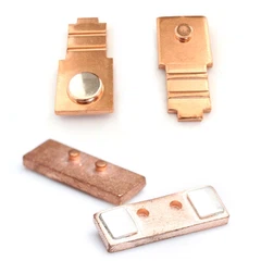
CuW contacts are commonly used on main power switching interfaces because tungsten particles improve arc resistance while copper provides thermal conduction.
AgWC materials are selected when higher electrical conductivity and reduced contact welding risk are required. The silver matrix provides stable contact resistance, while tungsten carbide particles improve resistance against mechanical wear and arc damage.
Material Selection Factors Under IEC 60947 and Railway Applications
Contact hardness: controlled according to switching energy requirements
Density consistency: controlled during powder metallurgy production
Surface flatness: maintained within ±0.01mm machining tolerance
Contact interface cleanliness: controlled before brazing assembly
Request Free DFM Evaluation & Quote
Vacuum Brazing Assembly: Joining Large CuW Contacts with Thick Copper Terminals
The connection between CuW contact tips and copper terminals is one of the highest-risk manufacturing steps in heavy-duty DC contactor production.
Traditional mechanical fastening methods may introduce increased electrical resistance and mechanical fatigue points. Vacuum brazing creates a metallurgical bond between dissimilar materials while maintaining current-carrying capability.
Apollo applies brazed contact assembly processes including:
Vacuum brazing
Resistance silver brazing
Molecular diffusion welding
Precision stamping of copper carriers
CNC finishing and CMM inspection
Brazing Process Parameters for Copper Contact Assembly
| Process Parameter | Engineering Requirement |
| Brazing atmosphere | Vacuum-controlled environment |
| Base material | C1100 pure copper + CuW / AgWC |
| Joint strength verification | Tensile and shear testing |
| Thermal cycling | -40°C to +125°C validation |
| Interface quality | No visible cracks or voids |
| Dimensional tolerance | ±0.01mm |
Vacuum brazing reduces interface resistance by creating direct metallic bonding. The brazing filler alloy composition, heating profile, and cooling rate directly affect joint reliability.
For rail transit applications, brazed contact assemblies must maintain electrical performance after long-term vibration exposure. Metallurgical inspection is used to verify bonding quality and prevent hidden defects such as incomplete wetting and internal porosity.

Precision Metal Manufacturing: IATF 16949 Control from Stamping to Final Inspection
Heavy-duty DC contactor components require stable geometry because contact alignment directly affects arc distribution and switching lifetime.
Apollo manufacturing processes include precision stamping, machining, brazing, and inspection systems controlled under automotive-grade quality procedures.
Manufacturing Process Flow with Quality Control Standards
| Manufacturing Stage | Process Technology | Quality Control Method |
| Copper terminal forming | Precision stamping | Dimensional inspection |
| Contact preparation | Powder metallurgy machining | Density and hardness testing |
| Contact joining | Vacuum brazing | Metallographic analysis |
| Surface finishing | Grinding and cleaning | Surface roughness testing |
| Final assembly | Component integration | CMM inspection |
| Quality approval | PPAP Level 3 | Full documentation package |
Key manufacturing capabilities:
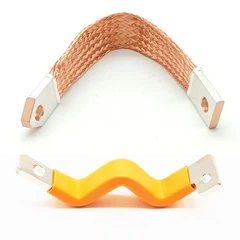
C1100 pure copper stamping
C2680 brass precision forming
CuW / AgWC brazed contacts
Laser welding Cu-Al components
CMM dimensional inspection
Resistance measurement testing
Traceability management under IATF 16949
Dimensional Stability Requirements for Contact Alignment
Contact misalignment can increase arc duration and accelerate erosion.
Typical controlled dimensions include:
Contact height tolerance: ±0.01mm
Terminal position tolerance: ±0.02mm
Flatness requirement: controlled by precision grinding
Surface roughness: optimized for contact pressure stability
Thermal Shock and Insulation Validation: -40°C to +125°C Reliability Testing
Rail transit and renewable energy systems require DC contactors to operate across wide temperature ranges. Thermal expansion differences between copper terminals, ceramic insulation components, and contact materials can create mechanical stress.
Validation testing normally includes:
| Test Item | Test Standard / Requirement |
| Thermal shock test | -40°C to +125°C cycles |
| Dielectric withstand test | >15kV/mm insulation capability |
| Insulation resistance test | High-voltage leakage monitoring |
| Vibration test | IEC 61373 railway standard |
| Salt spray test | Environmental corrosion evaluation |
| Contact resistance test | Micro-ohm measurement |
For renewable energy systems, DC contactors are installed inside battery cabinets, inverter systems, and power conversion equipment. Long service life requires stable insulation distance, corrosion resistance, and controlled thermal expansion.
Insulation Material Selection
| Insulation Method | Performance Characteristics | Application |
| Epoxy powder coating | High adhesion, corrosion protection | Metal housing and terminals |
| Thermoplastic insulation | High production efficiency | Electrical protection parts |
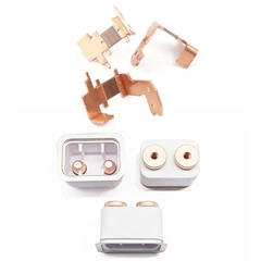
| Ceramic insulation | High temperature resistance | High voltage isolation |
Epoxy powder coating systems are commonly verified under UL 94 V-0 flame resistance requirements and environmental durability testing.
OEM Manufacturing Capability for Rail Transit and Renewable Energy DC Contactors
Apollo Electronic Components (Xiamen) Co., Ltd. provides OEM manufacturing support for heavy-duty DC contactor parts, including engineering review, material selection, tooling development, and mass production control.
Engineering support includes:
DFM evaluation before tooling
Prototype production for validation testing
PPAP Level 3 documentation
Material certification
Dimensional inspection reports
Reliability testing support
Production advantages:
IATF 16949-certified quality management
Precision stamping and welding capability
Copper and alloy material processing
Custom brazed contact assembly production
Stable supply for rail transit and energy infrastructure applications
Frequently Asked Questions
What documents are provided for PPAP Level 3 delivery of DC contactor components?
PPAP Level 3 packages include dimensional reports, material certificates, process flow charts, control plans, capability studies, and inspection records.
How does Apollo guarantee brazed contact assembly reliability for high current DC contactors?
Apollo uses vacuum brazing, metallographic inspection, resistance testing, and thermal cycling validation to verify CuW and copper terminal bonding quality.
What is the typical tolerance control for heavy-duty DC contactor copper parts?
Precision copper components are controlled with CMM inspection and dimensional tolerances typically within ±0.01mm for critical contact alignment features.
contact us

Send Inquiry