



Application and Engineering Technical Essentials of Heat-Shrinkable Materials for Busbar Insulation Protection in Substations
Sep 19, 2026
Leave a message
As substation electrical equipment evolves toward higher voltages, larger capacities, and more compact designs, the insulation protection of busbars, connection points, and other exposed conductors has garnered increasing attention. In actual operating environments, factors such as humidity, condensation, salt spray, industrial pollution, ice accretion, and the intrusion of small animals can compromise the withstand capability of electrical clearances and insulation surfaces, thereby increasing the risks of pollution flashover, surface discharge, phase-to-phase short circuits, and equipment corrosion. For substations with long service lives and switchgear with limited space, applying heat-shrinkable materials-which offer stable insulation performance-to protect exposed conductors is a common technical approach to improving the equipment's operating environment.

Heat-shrinkable insulation materials are polymers characterized by shape-memory properties. During manufacturing, their internal molecular structure is typically modified via radiation or chemical cross-linking, allowing the material to retain specific dimensions after expansion, setting, and cooling. When subsequently exposed to heat at a specified temperature, the internal cross-linked structure triggers a recovery effect, causing the material to shrink back to its original dimensions. Leveraging this property, heat-shrinkable tubing or tape can be applied to busbars, conductors, and connection points; controlled heating then causes the material to form a tightly fitting insulation layer over the protected component.
In substation applications, the primary function of heat-shrinkable materials is not to alter the conductivity of the busbar itself, but to establish a continuous insulating protective layer around the conductor. Depending on equipment configuration and installation conditions, various forms may be employed, such as heat-shrinkable busbar tubing, heat-shrinkable insulation tape, insulating shrouds, and creepage-enhancing structures. For straight sections of exposed busbar, tubing products offer structural integrity and a neat appearance; for busbars that are already installed and difficult to disassemble, heat-shrinkable tape allows for on-site insulation treatment via wrapping; and for busbar joints, corners, and irregularly shaped connection areas, appropriate protection methods must be selected based on the specific structural configuration.
From an electrical design perspective, the use of heat-shrinkable materials mitigates the risks associated with exposing conductors directly to the external environment. For instance, within switchgear cabinets, insulating the busbars reduces the likelihood of direct contact between conductors and foreign objects. In compact equipment, proper insulation protection can facilitate the optimization of electrical clearances. However, the application of insulation sleeving does not simply equate to an unlimited reduction of phase-to-phase spacing; actual designs require comprehensive verification based on system voltage levels, insulation material properties, creepage distances, pollution levels, and relevant standards.

When combining heat-shrink materials with copper busbars, factors such as the conductor surface condition and thermal cycling requirements must be considered. While copper busbars offer excellent electrical and thermal conductivity, their surfaces are susceptible to oxidation or corrosion when exposed to humidity, salt spray, or corrosive gases over extended periods. For customized copper busbar connections with heat-shrink tubing intended for long-term outdoor operation, particular attention should be paid to the adhesion between the insulation and the copper conductor, the integrity of end-sealing, and interface stability following prolonged thermal cycling.
A key function of busbar insulation is to mitigate the impact of environmental factors on electrical equipment. In coastal regions, airborne salt tends to accumulate on insulation surfaces and near conductors, creating a conductive pollution layer; in industrial zones, acidic or alkaline gases and particulate matter can accelerate metal surface corrosion. Prolonged exposure of conductors can lead to the accumulation of contaminants, potentially forming localized conductive paths. Consequently, applications utilizing heat-shrink insulation on copper busbars require a balanced consideration of electrical insulation, environmental resistance, and long-term mechanical stability.
Heat-shrink materials can also be applied in substation areas prone to condensation. Condensation may form on the surfaces of conductors and insulating components when humidity is high, and equipment temperatures fluctuate. The resulting water film significantly alters the electric field distribution and leakage paths across the insulation surface, creating conditions that-particularly in polluted environments-can trigger surface discharge. While a continuous heat-shrink insulation layer reduces direct moisture contact with exposed conductors, high-humidity environments still necessitate systematic control measures, including equipment sealing, ventilation, heating/dehumidification, and optimized insulation structural design.
For outdoor equipment, ice accumulation can also alter the electrical characteristics of the insulation structure. The combined effects of ice layers, meltwater films, and contaminants can modify the effective creepage path across insulator surfaces. Therefore, for equipment requiring enhanced surface insulation protection, a combination of heat-shrink materials and auxiliary insulation structures can be employed to improve operational reliability. When using heat-shrink sleeve-insulated copper busbars, the material's weather resistance, UV resistance, and low-temperature performance must be verified based on the installation environment; judgments should not be made solely on the basis of insulation data applicable to indoor operating conditions.
The design of the heat-shrink insulation layer must also account for the busbar's operating temperature. Busbars generate Joule heat when carrying rated current, and the resulting temperature rise depends on factors such as the conductor's cross-sectional area, material resistivity, ambient temperature, and heat dissipation conditions.
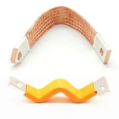
Adding an insulation layer alters the equipment's heat exchange path; therefore, one cannot simply assume that "encapsulating with insulation material will inevitably reduce heat dissipation" or "will have no impact on temperature rise." In actual engineering practice, verification should be conducted through thermal calculations, temperature rise tests, or on-site temperature measurements. For new energy electrical connection structures-such as flat copper battery busbars with heat-shrink tubing-special attention must be paid to thermal cycling caused by continuous high-current operation, cyclic loading, and frequent charging and discharging.

The flame-retardant performance of heat-shrink materials is another critical factor in the selection of power equipment components. If electrical insulation materials are exposed to localized overheating, arcing, or other heat sources, their combustion characteristics directly influence the potential extent of equipment failure propagation. Consequently, when using structures such as copper flat square busbars with PVC heat-shrink tubing in power equipment, it is essential to verify the insulation layer's flame-retardant rating, heat resistance range, and compliance with the specific fire safety requirements of the equipment. For enclosed switchgear, additional factors such as smoke generation, dripping during combustion, and long-term thermal aging must also be comprehensively considered.
Material aging resistance also determines the actual service life of the insulation protection system. After prolonged exposure to the combined effects of temperature, electric fields, UV radiation, humidity, and mechanical stress, heat-shrink materials may undergo hardening, cracking, discoloration, a decline in shrinkage performance, or interfacial delamination. Therefore, selection criteria should not focus solely on initial dielectric strength but must also consider performance changes resulting from long-term thermal aging, hygrothermal aging, environmental aging, and electrical aging. For copper busbars with heat-shrink insulation intended for long-term operation, appropriate material validation protocols and maintenance schedules should be established based on the equipment's expected service life.
The quality of the heat-shrink material's installation also directly impacts the final performance of the insulation system. Excessively low heating temperatures may result in insufficient material shrinkage, creating localized gaps between the conductor and the insulation layer; conversely, excessively high temperatures can cause surface overheating, localized damage, or even alterations to the material's properties. Therefore, during installation, the heat source temperature, heating distance, and movement speed must be controlled in accordance with material specifications to ensure a uniform shrinking process throughout.
Special attention must be paid to ends and corners during the installation of heat-shrink tubing. While uniform shrinkage is relatively easy to achieve on straight sections, areas such as busbar bends, bolted connections, and irregular geometries are prone to material bunching or incomplete shrinkage. Improper treatment of the ends can allow moisture and contaminants to penetrate the edge of the insulation layer, creating long-term operational risks. Consequently, the end sealing, insulation transition, and mechanical fixation methods must be clearly defined in the installation plan.
Busbar joints are critical areas for insulation protection. Because these joints facilitate both mechanical connection and current transmission, they often feature bolts, washers, and contact interfaces, resulting in a more complex structure than straight busbar sections. When covering joints with heat-shrink materials, care must be taken to avoid compromising connection tightness, contact resistance, or future maintenance access. For connections requiring periodic disassembly, a maintainable insulation protection structure is preferable to fully sealing and fixing the entire area.
For electrical connection products, the conductor material and surface treatment also influence the suitability of the heat-shrink protection scheme. For instance, while pure solid copper busbars offer excellent conductivity, the oxidation state, cleanliness, and roughness of the copper surface affect how well the insulation material adheres. If the conductor features surface treatments such as tin or nickel plating, compatibility between the plating and the heat-shrink material must be verified, and the risk of interface delamination following thermal cycling must be assessed.
In new energy power systems, the application of heat-shrink insulated busbars has expanded beyond traditional substations to include electric vehicles, energy storage systems, charging infrastructure, and power electronics. New energy equipment is characterized by high currents, high power density, and compact designs; consequently, conductive connectors must not only meet current-carrying requirements but also address insulation, short-circuit prevention, mechanical installation, and space utilization. Therefore, conductor-insulation assemblies-such as copper busbars with tin-plated heat-shrink tubing-offer excellent adaptability for electrical connection designs in new energy applications.
In electric vehicles and energy storage systems, busbars must typically facilitate power transmission between batteries, capacitors, inverters, and other high-voltage components within confined spaces. Compared to bare copper busbars, those featuring an insulating heat-shrink layer reduce the risk of accidental contact between conductors or between conductors and metal housings, while also allowing for structured layouts tailored to the equipment's internal space. When utilizing copper busbar connectors with insulated heat-shrink tubing, engineering designs must comprehensively evaluate factors such as terminal structure, installation orientation, minimum bending radius, and insulation clearance.
In the high-voltage electrical systems of new energy vehicles, busbars often form tight connections with components such as film capacitors, contactors, fuses, and battery modules. These systems impose stringent requirements regarding electrical clearance, voltage withstand capability, and thermal management; consequently, the choice of insulation layer cannot be based solely on appearance or experience with conventional low-voltage applications. Parameters such as material dielectric strength, operating temperature, flame retardancy, chemical resistance, and long-term electrical stability must all be incorporated into the engineering validation process.
From a maintenance perspective, heat-shrink insulation protection reduces the likelihood of external contamination affecting exposed conductors, but it does not eliminate the need for equipment inspections. Operations and maintenance personnel must still regularly inspect the insulation surface for anomalies such as cracks, aging, discoloration, bulging, ablation, or edge delamination. For busbars subjected to short-circuit currents, overloads, or severe thermal shock, specific attention should be paid to checking for thermal damage beneath the insulation layer and at conductor connection points.
Creepage distance and electrical clearance are two distinct concepts that must be clearly differentiated when applying heat-shrink materials. Electrical clearance refers to the shortest distance through the air between conductors at different potentials, whereas creepage distance is the shortest path along the surface of the insulating material.
While heat-shrink materials alter the conductor's exposure status and the surface structure of the insulation, their actual insulating performance depends on material thickness, surface condition, pollution levels, and structural design. For high-voltage equipment, simply increasing the thickness of the heat-shrink layer cannot substitute for a comprehensive insulation coordination design. When selecting heat-shrinkable materials for specialized environments, the environmental classification must be taken into account.
For instance, equipment in coastal areas requires a focus on salt spray and hot-humid conditions; industrial zones necessitate consideration of corrosive gases; cold regions demand low-temperature flexibility and heat-shrinkage performance; and outdoor equipment requires resistance to UV radiation and long-term weathering. Insulation material formulations and structures should be tailored to the specific operational conditions of each application scenario.
As the trend toward miniaturization and high power density in electrical equipment continues, the value of heat-shrinkable insulation protection will extend beyond traditional substation retrofitting into sectors such as new energy vehicles, energy storage, power electronics, rail transit, and industrial power distribution. Future heat-shrinkable insulation technology will place greater emphasis on temperature ratings, flame retardancy, arc resistance, environmental stability, and automated installation processes, while evolving from simple insulation protection toward integrated designs that combine electrical conduction, insulation, mechanical fixation, and system integration.

Overall, heat-shrinkable materials offer a flexible insulation solution for bare busbars and electrical connection points. Their engineering value lies primarily in mitigating electrical risks associated with environmental contamination, contact by small animals, condensation, and accidental contact, while also providing greater design flexibility for the insulation structures of compact electrical equipment. Material selection should be based on system voltage, operating temperature, current-carrying capacity, insulation class, environmental conditions, and maintenance requirements; long-term operational reliability must be ensured through standardized installation and necessary verification of electrical and thermal performance.
For electrical connection projects requiring simultaneous compliance with standards for electrical conductivity, insulation, dimensional fit, and mass production, the engineering procurement phase should prioritize the verification of copper specifications, surface treatments, Copper Busbar with Heat Shrink Tube Insulation material properties, insulation thickness, and terminal configurations, alongside prototype validation under actual operating conditions.
contact us

Send Inquiry