










Analysis of Safety Structures for Prismatic Aluminum-Cased Power Battery Covers: Synergistic Protection via OSD, Fuse, and Explosion-Proof Valve
Sep 15, 2026
Leave a message
With the rapid development of new energy vehicles, energy storage systems, and electric transport, the requirements for the safety, reliability, and consistency of power and energy storage batteries continue to rise. As the core unit of a battery system, the power battery cell not only handles energy storage and release but also features internal pressure, temperature, electrochemical reactions, and mechanical structural states that directly impact the safety of the entire unit. Consequently, in prismatic aluminum-cased battery designs, safety mechanisms-such as pressure relief, current interruption, and responses to abnormal conditions-receive as much industry attention as fundamental components like terminals, cover plates, and casings.
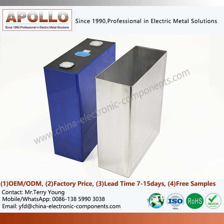
Prismatic aluminum-cased batteries typically utilize metal casings, offering high structural strength, efficient space utilization, and ease of modular integration. In applications such as new energy vehicles and energy storage systems, these cells must withstand various operating conditions, including charging, discharging, temperature fluctuations, and mechanical vibrations. Should issues like overcharge, internal short circuits, abnormal heating, or continuous gas accumulation occur, internal pressure can rise rapidly; therefore, safety mechanisms on the cover plate must execute appropriate protective actions corresponding to the specific stage of the fault.
From a safety design perspective, the safety mechanisms within the cover plate of a prismatic aluminum-cased battery do not constitute a simple, singular protective component but rather a multi-level protection system driven by various triggering mechanisms. Representative components in traditional designs include the Overcharge Safety Device (OSD), the current-interrupting fuse, and the pressure-relief mechanism (explosion-proof valve). These three components address risks associated with abnormal voltage, current, and internal pressure, respectively, performing distinct safety functions at different stages of a fault.
Under normal operating conditions, the battery's internal components maintain stable electrical connections and mechanical integrity. When abnormal charging or other faults occur, internal electrochemical reactions may generate excess gas, causing internal pressure to rise gradually. If the abnormal condition persists, energy input must first be reduced via electrical or mechanical means; if pressure subsequently exceeds the limits the casing and sealing structures can withstand, the pressure-relief mechanism must vent the internal gas. Thus, battery safety design typically follows a "defense-in-depth" strategy, progressing from anomaly detection to current interruption, and finally to pressure relief in extreme scenarios.
Working Principle of the OSD (Overcharge Safety Device)
The OSD-or Overcharge Safety Device-is a mechanical safety mechanism used in certain prismatic aluminum-cased battery designs to protect against overcharge anomalies. Its primary function is not merely to vent pressure directly, but to trigger a mechanical action once internal pressure reaches a set threshold, thereby placing the circuit into a specific protective state.
In some traditional designs, the OSD is positioned near the negative terminal and consists of a metal component capable of elastic deformation. Under normal operating conditions, this component maintains a prescribed state of insulation or connection relative to surrounding conductive structures. When the battery undergoes overcharge accompanied by internal gas generation, pressure rises; once the design trigger range is reached, the metal element (often a snap-action disc) deforms and shifts position, establishing a specific electrical path with relevant conductive components.
The critical value of this mechanical action lies in its ability to convert internal pressure changes into changes in circuit status. Unlike systems that rely entirely on electronic controls to detect anomalies, this mechanical trigger mechanism responds independently, serving as a supplementary safety feature within the battery system.
It is important to note that the specific structure, trigger pressure, and actuation method of an OSD vary across different battery products. As cell architectures, rated voltages, capacities, and safety strategies evolve, some newer battery cover designs have replaced or redesigned the traditional OSD approach in favor of alternative protective structures. Consequently, designing a battery cover requires selecting an appropriate protective structure based on the specific cell chemistry, pressure characteristics, and safety standards, rather than simply applying fixed parameters.
Fuse Structures and Abnormal Current Protection
While the OSD primarily serves a mechanical triggering function, the fuse is responsible for interrupting the circuit during abnormal current events. Certain abnormal battery conditions can generate instantaneous currents far exceeding normal operating levels; in such cases, a controllable fuse structure is required to rapidly sever the current path.
Fuses typically achieve a specific current-carrying capacity through the design of their cross-sectional area. They maintain stable conduction during normal charge and discharge operations; however, when an abnormal current exceeds the design limit, excessive Joule heating occurs in the localized area, causing the fuse element to heat up rapidly and melt, thereby breaking the electrical connection.
For battery systems, the design focus for a fuse is not simply to achieve the fastest possible interruption, but to strike a balance between operational reliability under normal conditions and response speed during anomalies. A fuse rating that is too low may lead to nuisance tripping during normal operation, whereas a threshold that is too high may fail to control fault currents promptly. Therefore, a comprehensive design approach is required, taking into account factors such as the cell's rated current, peak current, short-circuit current, ambient temperature, and connection structure.
In some battery designs, the fuse is integrated with the cover plate connector, terminal post, or other conductive structures to reduce the number of discrete components and shorten the path for abnormal currents. For high-energy-density lithium-ion batteries, current changes during an abnormal short-circuit event occur extremely rapidly; consequently, the geometry, material, resistance, and thermal response characteristics of the fuse structure must be rigorously validated.
The explosion-proof valve serves the function of releasing extreme pressure.
Internal pressure may continue to rise during severe thermal anomalies, internal short circuits, or sustained gas generation within the battery. If cutting off the current fails to halt the internal reaction, the pressure relief structure becomes a critical passive safety component.
Explosion-proof valves are typically integrated into the cover plate of prismatic aluminum-cased batteries, with the opening pressure controlled by a pre-designed weak point or zone. When internal pressure reaches the specified range, the valve ruptures or opens along this designed area, allowing internal gases to vent in a controlled direction and thereby reducing the risk of unintended casing rupture.
The explosion-proof valve is essentially a pressure management structure; its design must balance opening pressure, relief capacity, material strength, sealing performance, and the discharge path following activation. The opening pressure cannot be too low, as this could lead to accidental activation during normal production, transport, or use; conversely, it cannot be too high, as this might prevent timely pressure relief before the casing reaches its structural limit.
For energy storage systems and new energy vehicle battery packs utilizing lithium batteries, the explosion-proof valve must be designed in conjunction with the overall pack structure. Upon activation, high-temperature gases and electrolyte vapors must be vented in a direction that avoids direct impingement on adjacent cells, busbars, connectors, or other high-voltage components. Therefore, evaluating the mechanical properties of the valve in isolation is insufficient to meet actual safety requirements; system-level validation that considers the internal space of the battery pack and thermal runaway propagation paths is also essential.

Multi-level safety structures provide defense-in-depth
In terms of operating mechanisms, the OSD, fuse, and explosion-proof valve address different levels of safety risk. The OSD primarily relies on mechanical activation triggered by specific abnormal pressure conditions; the fuse focuses on interrupting abnormal currents; and the explosion-proof valve is designed for pressure relief during more extreme scenarios.
This layered design embodies the concept of "defense-in-depth" within the battery safety system. Under normal operating conditions, the various safety structures do not interfere with the battery's standard charge and discharge performance. When an anomaly occurs, these protective structures engage sequentially based on the severity of the fault; if electrical protection fails to fully contain the abnormal state, the mechanical pressure relief structure serves as the final line of passive defense.
In practice, not all battery cells utilize identical OSD (Overcharge Safety Device), fuse, and explosion-proof valve configurations. Variations in cell chemistry, capacity, rated voltage, and application scenarios necessitate different safety solutions for the cell cover assembly. Consequently, the engineering design process prioritizes a comprehensive failure mode analysis over a simple assessment of whether specific safety components are present.
The Cell Manufacturing Process Also Underpins Safety
Safety structures within the cover assembly fulfill only a portion of the battery's overall safety function; the cell manufacturing process itself directly impacts the reliability of the final product. Taking prismatic aluminum-cased cells as an example, manufacturing typically involves multiple stages: electrode preparation, cell assembly, casing encapsulation, electrolyte filling, formation, capacity grading, and testing.
Electrode manufacturing generally begins with mixing active materials, conductive agents, binders, and solvents to create a stable slurry, followed by coating, drying, calendering, and slitting. Factors such as slurry dispersion uniformity, coating thickness, areal density, and the quality of the electrode edges all influence subsequent electrochemical performance.
During the cell assembly stage, the positive electrode, negative electrode, and separator are combined-via winding or stacking-to form the bare cell. Connecting the electrode tabs to the current collectors typically requires welding processes tailored to the specific material system. The weld zone must possess sufficient mechanical strength while minimizing spatter, burrs, and localized heat-affected zones to prevent damage to the separator and other internal structures.
Subsequently, the bare cell is inserted into the aluminum casing, and the cover assembly is attached and sealed. Precision welding is commonly used to create a hermetic seal between the cover and the casing. For prismatic cells, the casing seam and the cover weld zone are critical points for maintaining airtightness; welding defects can lead to electrolyte leakage, moisture ingress, or the escape of internal gases, necessitating rigorous sealing and airtightness verification. Following electrolyte filling, the battery cell undergoes processes such as sealing, formation, and capacity grading.
The formation process activates the cell through a specific charge-discharge protocol and establishes a stable solid electrolyte interphase (SEI) layer.
Since formation parameters influence the cell's initial capacity, internal resistance, and subsequent cycling performance, rigorous process control is essential.
For products intended for energy storage systems, the cells must also be compatible with system-level structures, such as battery pack kits. This requires evaluating not only the performance of the cells themselves but also factors such as inter-cell connections, thermal management, insulation clearances, and fault isolation.
Impact of the Cover Plate Structure on Battery Reliability
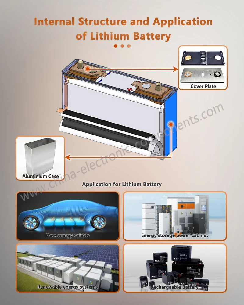
Although the cover plate of a prismatic aluminum-cased battery is relatively compact, it integrates terminals, sealing structures, explosion-proof mechanisms, and other electrical connection components, making it a critical functional area of the cell. The cover plate design must simultaneously address various requirements, including mechanical strength, insulation performance, airtightness, current-carrying capacity, and safety response capabilities.
First, the terminals and conductive connection structures must provide stable current-carrying capacity and maintain low contact resistance during long-term cycling. Second, the insulation structure must ensure adequate electrical isolation between the positive and negative terminals, as well as between the terminals and the casing. Third, the interface between the cover plate and the casing must maintain a stable seal to minimize the risk of moisture and contaminants entering the cell.
In high-capacity lithium-ion cells, the increased internal energy storage can lead to greater heat and gas generation during abnormal conditions; consequently, the mechanical design and safety response capabilities of the cover plate structure must be enhanced accordingly. Given the long operational lifespans and high number of charge-discharge cycles characteristic of energy storage applications, the fatigue resistance, corrosion resistance, and long-term sealing stability of cover plate components are also critical areas of focus.
Expanding from Individual Cells to Energy Storage Systems
As the new energy industry continues to evolve, battery applications have expanded beyond automotive powertrains to encompass residential energy storage, C&I (commercial and industrial) energy storage, backup power for telecommunications, and large-scale grid energy storage. Different application scenarios impose distinct requirements on battery safety structures. In the sectors of residential and commercial/industrial energy storage, lithium battery packs for solar energy storage systems typically operate in relatively fixed environments; however, due to their long operational lifecycles and large system capacities, long-term reliability, thermal management, and fault isolation capabilities are of paramount importance.
For residential energy storage units, lithium-ion batteries must not only meet basic energy storage requirements but also account for space constraints, ambient temperature fluctuations, and ease of maintenance. The safety structure of the cell cover plate must function in coordination with the battery management system (BMS), the enclosure structure, and the thermal management system.
In energy storage systems paired with renewable energy sources, lithium-ion batteries frequently undergo charge-discharge cycles; consequently, cell consistency and cycle stability serve as critical foundations for system design. Simultaneously, the internal interconnection structures and safety components of the battery pack must be robust enough to withstand long-term operational conditions.
As battery systems become increasingly modular, the design of lithium-ion battery packs has shifted from focusing solely on individual cell performance to prioritizing system-level safety management. This encompasses multiple layers, including cell monitoring, temperature detection, overcurrent protection, insulation monitoring, and fault isolation.
Safety Structure Design Across Different Battery Chemistries
The market currently features a diverse range of lithium battery chemistries; different cathode materials and electrochemical systems exhibit varying levels of thermal stability, operating voltage, and energy density. For instance, LiFePO4 (LFP) power cells offer superior thermal stability, making them widely adopted in energy storage applications, whereas high-energy-density systems may require a greater focus on thermal management, structural integrity, and protection against thermal runaway.
Regardless of the chemistry employed, safety structure designs must be validated based on specific material systems and operating conditions. Pressure parameters, current ratings, or explosion-proof structures associated with one type of cell cannot simply be applied as a universal design standard for all products.
For large-scale energy storage systems, the issue of thermal propagation between cells requires further consideration. When an anomaly occurs in a single cell, the safety structure must not only contain the risk associated with that specific cell but also minimize the likelihood of the anomaly spreading to adjacent cells. Therefore, cell-level protection, module-level isolation, and system-level fire suppression and venting designs must be integrated to form a comprehensive safety chain.
Coordinated Design of Explosion-Proof Valves, Sealing, and Gas Management
An explosion-proof valve does not function in isolation; it is directly linked to the cell casing, the cover plate sealing structure, and the system's venting channels. Under normal operating conditions, the battery interior must maintain a high level of airtightness to prevent the ingress of moisture and external contaminants, while also ensuring that the internal electrolyte does not leak through the cover plate assembly area. In the event of abnormal gas generation, the explosion-proof mechanism must activate promptly at the designed pressure threshold.
Consequently, the engineering validation phase typically focuses on factors such as airtightness, activation pressure, pressure relief direction, and structural integrity following activation. For cells of varying capacities, assessments must also account for gas generation rates and internal spatial constraints; this ensures the explosion-proof structure meets sealing requirements during normal operation while providing sufficient pressure relief capacity under abnormal conditions.
Battery Safety: From "Single-Point Protection" to System-Level Synergy
In recent years, battery structural design has evolved from relying on single-component protection to a multi-layered, synergistic safety approach. While past efforts focused primarily on whether individual cells possessed explosion-proof and overcurrent protection capabilities, current engineering designs emphasize the synergy between materials, cells, cover plates, modules, battery packs, and control systems.
For applications such as high-energy-density "Lithium SuperPack Batteries," system designers must simultaneously address internal cell safety, electrical protection, thermal management, and mechanical protection. Although the safety components on the cover plate are small in size, they play a critical role in providing protection during abnormal events; therefore, their manufacturing precision and consistency are paramount.
In the new energy vehicle sector, battery systems are evolving toward higher voltages, higher energy densities, and greater integration; in the energy storage sector, system capacities and operational lifespans are steadily increasing. These trends place higher demands on the structure of battery cell covers. Future cover designs will likely prioritize functional integration, miniaturization, high reliability, and smart capabilities, while enhancing safety responses during abnormal conditions through precise pressure control and material optimization.
Key Focus Areas for Battery Cover Quality Control
From a manufacturing perspective, battery covers are precision metal components; quality control encompasses not only dimensional accuracy but also material properties, stamping, welding quality, surface finish, insulation performance, and airtightness.
For stamped components, it is essential to control material thickness, forming dimensions, and localized deformation to prevent excessive residual stress from affecting subsequent assembly. For thin-walled or scored structures-such as explosion-proof valves-critical controls focus on structural dimensions and local strength to ensure the actual activation pressure remains within design specifications.
Welding processes require close monitoring of weld continuity, penetration depth, porosity, spatter, and the heat-affected zone. For the hermetic weld joining the cover to the casing, comprehensive assessment must also incorporate airtightness testing.
In mass production, consistency is often more critical than the performance of an individual sample. Consequently, production processes must establish stable operating windows and continuously monitor product quality through dimensional inspection, visual inspection, airtightness testing, and functional verification.
Future Trends in Safety Structures for New Energy Batteries
As the new energy industry expands, battery safety technology will continue to focus on high energy density, high integration, and long-term reliability. For power batteries, increasing cell dimensions and rising system voltages necessitate simultaneous improvements in the cover's current-carrying capacity, insulation, and safety pressure-relief capabilities.
In the energy storage sector, lithium-ion energy storage systems typically require longer operational lifespans and higher capacities, placing greater emphasis on long-term cycling reliability, thermal safety, and fault isolation capabilities.
Simultaneously, battery manufacturing is evolving toward automation, digitalization, and precision. Technologies such as in-line dimensional inspection, welding process monitoring, airtightness testing, and production data traceability enable further improvements in the consistency of battery covers and cells. For safety structures, the digitalization of the manufacturing process enables manufacturers to more accurately identify potential quality fluctuations and mitigate the risk of failure during mass production.
Overall, the safety structures within the cover plates of prismatic aluminum-cased batteries are a vital component of the cell's safety system. Features such as the OSD (Overcharge Safety Device), fuse, and explosion-proof valve protect distinct mechanisms-mechanical triggering, abnormal current cutoff, and pressure relief, respectively-while cell manufacturing, welding and sealing, material selection, thermal management, and battery management systems collectively form a comprehensive safety framework.
As new energy vehicles and energy storage systems evolve toward higher capacity, higher voltage, and greater integration, battery safety is no longer an issue confined to a single component; rather, it is a systems engineering challenge that spans materials, cell manufacturing, structural design, interconnection systems, and end-use applications. Looking ahead, battery cover plates and their safety components will continue to advance in terms of miniaturization, precision, reliability verification, and multifunctional integration, thereby providing a more robust structural foundation for the long-term, stable operation of power and energy storage batteries.
From an engineering procurement perspective, the selection of battery cover plates and related precision metal safety components should prioritize the evaluation of material systems, dimensional consistency, forming and welding processes, airtightness, and safety structure verification capabilities, with choices aligned to the specific technical requirements of the battery cells and systems.
contact us
Send Inquiry