










Technical Analysis Of Copper Busbars For Energy Storage: Material Selection, Insulation Protection, Current-Carrying Design, And Surface Treatment Processes
Sep 26, 2026
Leave a message
As energy storage systems evolve toward higher voltages, larger capacities, and higher power densities, copper busbars have transitioned from simple conductive connectors into critical components that influence the system's electrical performance, thermal management, insulation safety, and structural reliability. Components such as battery clusters, busbar units, Power Conversion Systems (PCS), DC distribution units, and capacitor connection circuits all require well-designed conductive structures to ensure stable power transmission. Consequently, the design of copper busbars-encompassing material selection, cross-sectional dimensions, insulation methods, connection structures, and surface treatments-must be comprehensively tailored to actual operating currents, voltage levels, temperature rise limits, and installation environments.
From manufacturing and application perspectives, there is no single, fixed design solution for energy storage copper busbars. Factors such as current ratings, spatial layouts, insulation clearances, and environmental conditions directly dictate the choice of materials and fabrication methods. This is particularly true for high-voltage energy storage systems, where both electrical conductivity and insulation performance must meet stringent requirements. Simply increasing the conductor's cross-sectional area or the insulation thickness cannot resolve every engineering challenge; instead, a balanced approach is required to optimize current-carrying capacity, heat dissipation, electrical clearance, creepage distance, and mechanical structure.
Material Selection and Performance Fundamentals for Energy Storage Copper Busbars
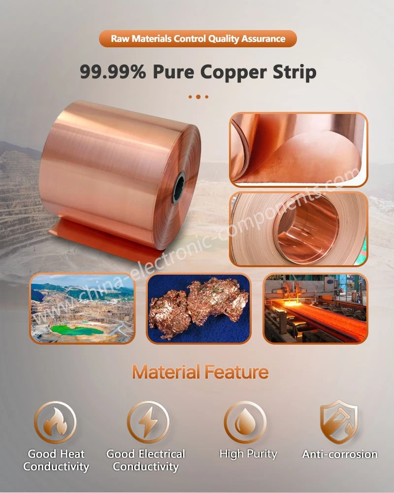
Copper is a widely used conductive material in energy storage systems, prized for its high electrical conductivity, excellent thermal conductivity, and superior ductility and machinability. In high-current DC connection scenarios, utilizing the appropriate grade of pure copper (such as oxygen-free or tough-pitch copper) minimizes conductor resistance and Joule heating during operation, thereby laying the foundation for the system's long-term, stable performance.
Common copper busbar materials include T1 and T2 grades, as well as various copper alloys. T1 copper offers high purity and conductivity, making it suitable for electrical connections where minimizing resistive loss is critical. T2 copper strikes an optimal balance between conductivity, machinability, and cost, leading to its widespread use in energy storage, power distribution, and power electronics. For standard high-current connections, material selection is typically based on a comprehensive assessment of current-carrying capacity, mechanical strength, fabrication methods, and cost, rather than relying solely on copper purity.
In practical engineering applications, the cross-sectional area of the copper busbar is determined based on continuous operating current, permissible temperature rise, installation method, ambient temperature, and heat dissipation conditions. Current density can serve as a preliminary design reference, but final dimensions must be verified through temperature rise calculations or actual testing. For space-constrained high-power equipment, conductor width, thickness, and length must be designed in coordination with terminal locations, bending radii, and insulation structures.
Compared to copper, aluminum has a lower density, making it valuable for weight-sensitive energy storage equipment. However, since aluminum has lower electrical conductivity than copper for a given cross-sectional area, a larger cross-section is typically required to meet the same current-carrying capacity. Additionally, aluminum surfaces readily form an oxide layer; therefore, contact interfaces and electrochemical corrosion must be carefully considered at connections involving dissimilar metals.
For energy storage projects located in coastal, high-humidity, or high-temperature environments, or areas with corrosive gases, long-term environmental adaptability must be considered during material selection. Under these conditions, the corrosion resistance of the connection structure can be enhanced through material system optimization, surface plating, and insulating encapsulation.
Structural Design and Current-Carrying Capacity of Energy Storage Copper Busbars
The core function of energy storage copper busbars is to establish a low-impedance, highly reliable path for current transmission. While a larger cross-sectional area theoretically results in lower DC resistance, the actual design involves more than simply increasing thickness; busbar dimensions are constrained by installation space, weight, bending requirements, heat dissipation conditions, and connection terminals.
In high-current DC applications, conductor temperature rise stems primarily from resistive losses. As operating current increases, the heat generated by the busbar rises significantly; designers must therefore consider both the conductor's own heat dissipation and the impact of surrounding components on heat transfer. In enclosed electrical cabinets and energy storage battery compartments, internal airflow is typically more restricted than in open environments, meaning a busbar of the same size may exhibit different actual current-carrying capacities depending on the installation environment.
Busbar orientation also affects heat dissipation. Facilitating natural convection paths can help lower the conductor's surface temperature; for high-power systems, designs may incorporate forced-air cooling, liquid cooling, or other thermal management structures. Thermal design should not focus solely on the busbar itself but must also analyze temperature variations at connection points, within insulation layers, and across adjacent electrical components.
For connection structures required to carry high currents over long periods, engineering verification typically includes temperature rise tests, insulation tests, and connection resistance tests. By applying current under actual operating conditions, one can observe temperature changes in the copper busbar and its connection points, thereby verifying whether the design meets specified temperature-rise requirements.
Insulation Design for Energy Storage Copper Busbars
In high-voltage energy storage systems, the insulation design of the copper busbar is just as critical as the conductor itself. The insulation structure must satisfy electrical safety requirements while also offering resistance to heat, mechanical stress, and environmental aging, as well as ensuring suitability for manufacturing processes.
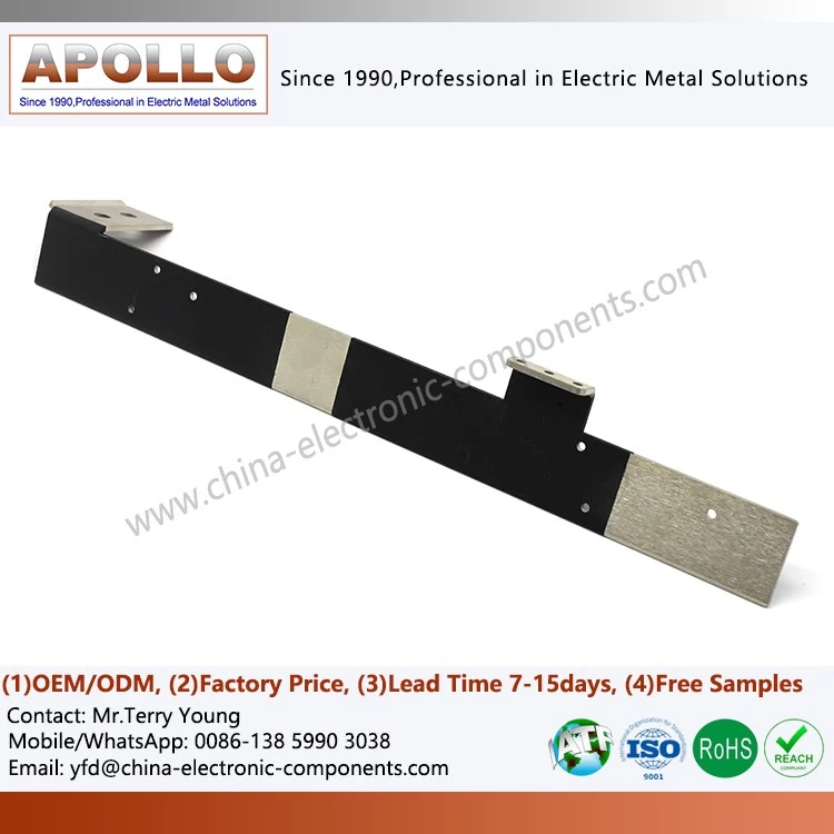
Common insulation methods include wrapping with insulating film, heat-shrink materials, epoxy resin coating, dip coating, and powder coating. Different processes are suited to different busbar configurations. For instance, conductors with simple structures and regular shapes can be insulated via continuous wrapping; conversely, for busbars featuring complex bends, holes, and terminal geometries, particular attention must be paid to ensuring the integrity of the insulation layer at edges, corners, and connection zones.
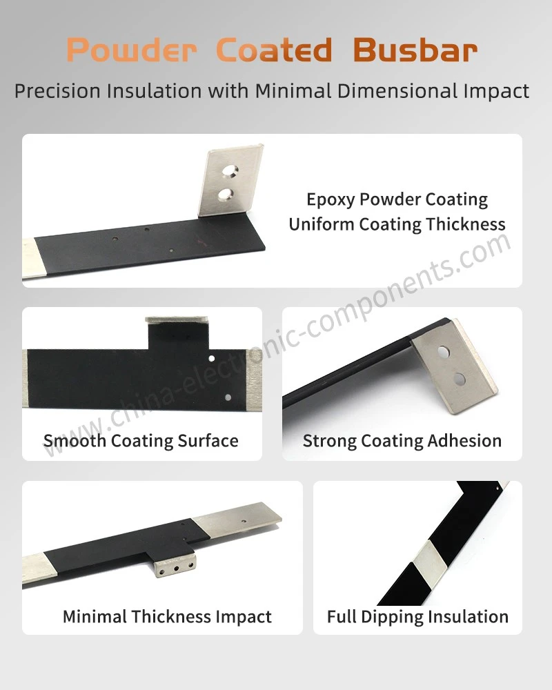
In powder insulation systems, a continuous insulation layer is formed on the conductor surface through processes involving pretreatment, heating, powder application, and curing. Process design must focus on factors such as surface cleanliness, pretreatment quality, coating thickness, and curing conditions to prevent defects like pinholes, air bubbles, delamination, or insufficient coverage.
For high-voltage connections in energy storage equipment, the insulation coating must provide mechanical protection in addition to electrical insulation. Damage to the insulation layer during transport, assembly, or prolonged vibration can expose the conductor and increase the risk of short circuits; consequently, coating adhesion and resistance to mechanical impact are key quality control metrics.
Epoxy Powder Insulation Technology and Applications
Epoxy powder is a widely used material for insulating copper busbars. Once cured, the epoxy coating offers excellent electrical insulation and mechanical stability, forming a continuous protective layer on the busbar surface.
The process typically begins with surface pretreatment to ensure the copper is clean and optimized for coating adhesion. An insulation layer is then applied-often via electrostatic spraying or other powder coating techniques-followed by heat curing to transform the powder material into a continuous, dense coating structure.
For copper busbars requiring bending, the adhesion between the coating and the substrate is critical. If significant bending is required after coating, the coating may crack or peel locally; therefore, the processing sequence is typically determined based on the product structure. For complex geometries, coating damage can be minimized by performing the insulation treatment after the busbar has been formed.
The thickness of the insulation layer on powder-coated busbars can be adjusted to meet specific voltage ratings, mounting configurations, and safety clearance requirements. However, a thicker insulation layer is not necessarily better; excessive thickness can increase the product's dimensions and weight while hindering heat dissipation and reducing available installation space. Consequently, the thickness must be carefully controlled in accordance with the required electrical insulation class.
In new energy vehicles and power electronics for energy storage, the insulation design for copper busbars must also account for high-frequency switching, electromagnetic environments, and the effects of thermal cycling. For high-power-density equipment, the insulation material must remain stable under conditions of prolonged temperature fluctuation and mechanical vibration.
Copper Busbar Surface Treatment and Oxidation Protection
While copper offers excellent electrical conductivity, its surface is susceptible to oxidation when exposed to air, moisture, or corrosive environments for extended periods. Surface treatment is therefore a standard functional process in the manufacturing of copper busbars for energy storage applications.
Tin plating is a widely used surface treatment method for copper busbars. Applying a tin layer enhances the conductor's oxidation resistance and provides a stable contact interface for bolted connections, terminal connections, and certain welding processes. Tinned copper busbars are particularly well-suited for electrical connections that require long-term contact stability.
The required plating thickness depends on the specific application, connection method, and environmental conditions. Outdoor energy storage systems generally require a greater focus on long-term performance in hot and humid, salt-spray, or corrosive environments, whereas indoor equipment may prioritize contact stability and manufacturing costs.
Nickel plating is another common surface treatment method. Nickel layers offer superior hardness, wear resistance, and corrosion resistance, providing distinct advantages in high-temperature environments or connection points subject to friction. For conductive components involving frequent mating/unmating or mechanical contact, a nickel layer helps minimize surface wear and improves long-term stability.
Additionally, organic anti-oxidation coatings can be used to protect the copper surface. Such coatings reduce direct contact between the copper and the surrounding air or moisture; however, careful attention must be paid to whether the coating interferes with subsequent welding, crimping, or electrical contact. Consequently, the product design phase must clearly define which areas require insulation and which must maintain conductive contact.
Process Control for Powder-Coated Copper Busbars
In energy storage systems, insulated busbars must simultaneously meet requirements for electrical conductivity, insulation, and mechanical structure; thus, process control during manufacturing directly impacts the final product's performance.
The manufacturing process typically involves cutting, punching, bending, surface pretreatment, powder coating, curing, and inspection. For products featuring multiple bends and mounting holes, a logical processing sequence must be established during the initial process design phase to prevent subsequent operations from damaging the insulation layer.
Coating uniformity is a key focus of quality control. If the coating is too thin in certain areas, it may fail to meet specified insulation requirements; conversely, if it is too thick, it may increase the product's dimensions and impede heat dissipation. Therefore, film thickness must be monitored during production, with particular attention paid to hole edges, bends, terminal ends, and geometric corners.
The bonding quality between the coating and the copper substrate is also critical. Inadequate surface pretreatment, insufficient curing temperatures, or unstable process parameters can compromise coating adhesion. For mass production, consistency across batches should be ensured through the recording of process parameters and in-process inspections.
Co-design of Bent Busbars and Insulation Structures
Internal space within energy storage equipment is often limited, requiring busbars to undergo multiple bends to connect battery clusters, power distribution units, and power conversion equipment. Therefore, the structural design of the busbar must account for both the electrical conduction path and the mechanical assembly path.
The design of epoxy powder-insulated bent busbars focuses on coordinating the bending radius, the integrity of the insulation layer, and the terminal connection areas. An excessively small bending radius can increase localized stress in the copper and subject the insulation layer to significant mechanical deformation, while an overly thick insulation layer may encroach upon the installation space required for complex configurations.
For high-voltage busbars, bending locations must also avoid the formation of excessively sharp geometric edges, as sharp corners can lead to localized electric field concentration. Therefore, while maintaining machining precision, applying appropriate edge rounding helps improve electrical clearance and the reliability of the insulation structure.
Connection Structure and Contact Reliability
Energy storage busbars must ultimately form a complete current circuit with batteries, switches, relays, fuses, and power electronic components via bolting, welding, crimping, or other connection methods.
The connection point is a critical area within the conductive system. Even if the busbar body itself has low resistance, issues such as oxidation, contamination, insufficient contact pressure, or inadequate contact area at the interface can lead to high contact resistance. As operating current increases, heat generation at the contact point rises; consequently, the connection structure requires specific validation regarding resistance and temperature rise.
For bolted connections, appropriate tightening torque must be determined based on materials, bolt specifications, and the connection structure, while anti-loosening measures ensure long-term stability. For welded structures, attention must be paid to the heat-affected zone, joint strength, and weld quality.
In certain high-voltage electrical connections, a clear distinction between insulated and conductive zones is required. The design of insulated, tinned solid copper busbar connectors focuses on simultaneously addressing the conductive contact surface and the surrounding insulation protection zone, ensuring the connection point balances low contact resistance with electrical safety.
Surface Treatment Selection for Energy Storage Busbars
There is no single surface treatment process suitable for every project. The choice of process depends on a comprehensive assessment of operating temperature, humidity, corrosion levels, connection methods, mechanical wear, and cost requirements.
Tin plating is suitable for connections requiring good oxidation resistance and contact stability; nickel plating is appropriate for applications demanding high wear, corrosion, and heat resistance; and organic coatings can provide environmental protection for non-contact areas.
For insulated busbars, compatibility between the surface treatment and the insulation coating must also be considered. Applying epoxy coatings to busbars requires ensuring good adhesion between the copper pretreatment, the plating layer, and the epoxy insulation system. If oil, oxides, or other contaminants are present on the busbar surface, adhesion issues may arise, even if the powder coating itself performs well.
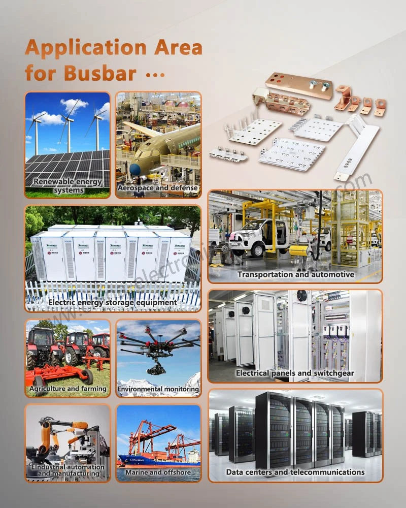
In new energy power electronics, the application of powder-coated EV busbars also requires design considerations regarding high-temperature cycling, vibration, and spatial layout. For high-voltage conductive components in vehicles and energy storage equipment in particular, the insulation layer serves not only to prevent electric shock and short circuits but must also maintain its integrity amidst prolonged vibration and temperature fluctuations.
Quality Verification System for Energy Storage Busbars
A comprehensive quality verification process for busbars should extend beyond mere dimensional accuracy; it requires a multi-dimensional inspection system covering everything from raw materials to the finished product.
Regarding materials, it is necessary to verify the copper grade, electrical conductivity, and mechanical properties. Dimensional checks must cover length, width, thickness, hole diameters, hole spacing, and bending dimensions. Surface inspections focus on the uniformity, adhesion, and visual quality of platings or coatings.
For insulated busbars, additional testing is required for insulation resistance, withstand voltage, and the detection of potential localized insulation defects. In the case of high-voltage energy storage systems, insulation performance verification must account for actual operating voltages, environmental conditions, and safety margins.
Regarding current-carrying capacity, temperature rise tests are used to verify the thermal performance of the busbar under specified operating currents. Testing must monitor temperature changes across the busbar body, connection points, and adjacent insulating materials, rather than simply measuring the surface temperature at a single location.
For equipment intended for long-term operation, environmental tests-such as thermal cycling, vibration, damp heat, and salt spray-can be employed to evaluate long-term product reliability. These tests help determine whether materials, surface treatments, and insulation structures remain stable throughout the actual operational lifecycle.
Future Trends in Busbar Technology for Energy Storage Systems
As energy storage systems evolve toward higher voltages, currents, and power densities, busbar design is shifting from traditional, purely conductive components toward integrated solutions that combine electrical, structural, and thermal management functions.
First, busbar structures are becoming increasingly compact. By optimizing cross-sectional shapes, bending paths, and connection methods, it is possible to enable shorter current paths with lower impedance within limited spaces.
Secondly, insulation technology will continue to evolve toward higher reliability. For high-voltage energy storage equipment, insulation layers must not only meet basic withstand-voltage requirements but also withstand long-term temperature fluctuations, hot and humid environments, mechanical vibrations, and electrical stress.
Thirdly, the automation of powder insulation processes will continue to advance. Technologies such as automated spraying, coating thickness measurement, visual inspection, and process data tracking help improve batch consistency for complex busbar products.
Furthermore, the synergistic design of busbars and thermal management systems is becoming increasingly important. For high-power energy storage systems, relying solely on natural heat dissipation is often insufficient; therefore, integrated designs combining busbar structures with air cooling, liquid cooling, and other thermal management components are required.
In certain high-voltage energy storage and new energy vehicle power electronics systems, busbars with insulated epoxy powder coatings allow for the integration of the conductor and insulation layer, thereby eliminating the need for additional insulation components and enhancing internal structural integration.
For applications requiring a balance of electrical conductivity, insulation performance, and mechanical reliability, copper busbars with epoxy powder insulation combine the busbar body with protective insulation, offering a more compact connection structure for high-voltage electrical systems.
Comprehensive Considerations in Engineering Selection
The design of energy storage busbars is not simply a matter of maximizing the thickness of the copper, insulation, or plating; rather, it requires a comprehensive engineering design logic based on actual operating currents, voltage ratings, temperature rise limits, installation space, connection methods, and environmental conditions.
For high-current systems, priority must be given to current-carrying capacity and temperature rise limits; for high-voltage systems, the focus should be on insulation clearance, coating integrity, and withstand-voltage capabilities; for outdoor energy storage equipment, factors such as humidity, heat, salt spray, and corrosive environments must be considered; and for high-power-density equipment, both the busbar structure and heat dissipation paths require optimization.
Consequently, a robust Epoxy Powder Insulated Bending Copper Busbar solution typically requires end-to-end control-spanning material selection, structural design, bending, surface treatment, and insulation processing through to final testing. Only by evaluating these stages as an integrated engineering system can one satisfy electrical performance requirements while simultaneously ensuring manufacturing efficiency, installation reliability, and long-term operational stability.
For engineering procurement and project selection, factors such as target current, voltage rating, installation space, insulation requirements, and the application environment should be considered in conjunction with the copper busbar manufacturer to jointly confirm materials, cross-sectional structure, surface treatment, and insulation process parameters, thereby finalizing the mass production plan during the sample verification stage.
contact us
Send Inquiry