



Risk Analysis Of Contactor Contact Welding: Formation Mechanisms, Influencing Factors, And Prevention And Control Technologies
Sep 16, 2026
Leave a message
Contactors are critical switching components in power control, power distribution equipment, and automation systems; their contacts are responsible for making and breaking load currents. In applications such as motor control, DC power distribution, new energy vehicles, energy storage systems, and industrial automation, contacts must repeatedly withstand switching currents, mechanical shock, and the thermal effects of electric arcs. When the arc energy generated during the breaking process exceeds the limits of the material and structure, localized melting, material migration, and re-solidification can occur on the contact surfaces, ultimately leading to a "weld" failure where the moving and stationary contacts cannot separate properly.
Contact welding is not caused by a single factor but results from the interplay of current, load characteristics, contact materials, mechanical structure, operating frequency, and the operating environment. This is particularly critical in high-current DC systems because DC lacks a natural zero-crossing point; the arc persists longer during the breaking process, placing higher demands on the contact material's resistance to welding, the arc-extinguishing structure, and the overall design of the contactor.
From an engineering perspective, understanding the mechanisms behind contact welding helps mitigate risks early in the stages of product selection, contact material design, arc-extinguishing system matching, and service life verification.

Basic Physical Mechanisms of Contact Welding
During normal contactor operation, the moving and stationary contacts gradually separate. Once the gap between the contacts reaches a certain distance, the current does not cease immediately but may continue to flow through the electric arc formed between them. The arc channel generates high temperatures, subjecting the contact surfaces to concentrated thermal stress. If the load current is high, the separation speed is insufficient, or arc-extinguishing conditions are inadequate, the arc energy can raise the temperature of localized contact areas to the melting point.
Once the contacts melt, material migration may occur due to the influence of the arc, contact pressure, and electromagnetic forces. As the contacts continue to move and the arc is eventually extinguished, the molten region re-solidifies, potentially forming a metallic bridge or a localized weld point between the two contacts. If the mechanical driving force is insufficient to overcome this bond during a subsequent attempt to break the circuit, the result is contact sticking or complete welding.
In high-current systems, the temperature rise on the contact surfaces is also influenced by contact resistance. Ideally, current should flow as uniformly as possible across the effective contact area; however, due to microscopic asperities on actual contact surfaces, the true conductive area is far smaller than the apparent contact area. When current concentrates on a limited number of microscopic contact points, local current density rises sharply, creating localized hot spots that can lead to material melting.
Over prolonged operation, contact materials may undergo changes such as diffusion, oxidation, and alloying. Material migration between dissimilar metals can alter the surface microstructure-affecting local melting points, hardness, and electrical conductivity-thereby further influencing resistance to contact welding.
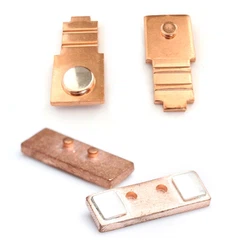
Performance is also influenced by contact structure, material combinations, and joining methods. For instance, brazed silver contacts-where the functional contact material is joined to the base-require careful attention to the bond strength of the interface, thermal conductivity, and stability during long-term thermal cycling.
Impact of Load Current and Breaking Conditions on Contact Welding
Load current is a critical factor influencing contact welding. When the operating current-or inrush, locked-rotor, or short-duration surge currents-exceeds the contactor's design limits, the thermal load and arc energy imposed on the contacts increase rapidly.
With inductive loads such as motors, transformers, and solenoid valves, significant back-electromotive force (back-EMF) is generated during current fluctuations. Upon circuit interruption, energy stored in the load and circuit inductance must be dissipated via arcing or an absorption circuit. Without effective surge suppression, the voltage across the contacts can spike rapidly, prolonging arcing duration and exacerbating contact damage.
This issue is particularly critical in DC applications. Unlike AC, which naturally passes through zero-current points-facilitating arc extinction-DC circuits lack this characteristic. Consequently, DC arc-extinguishing systems must actively enhance quenching capabilities through methods such as increased contact separation, magnetic blowouts, arc chutes, or other structural designs.
When selecting a contactor, safety cannot be determined solely by steady-state rated current; a comprehensive assessment must consider factors such as load type, inrush current, breaking current, switching frequency, and electrical life.
Contact Materials and Resistance to Welding
Contact materials directly determine a contactor's performance regarding electrical and thermal conductivity, wear resistance, resistance to arc erosion, and resistance to welding. In practical applications, the selection of an appropriate material system must be based on factors such as current rating, load type, mechanical lifespan, and environmental conditions, rather than relying solely on electrical conductivity as the evaluation criterion.
While pure silver offers high electrical and thermal conductivity-making it advantageous for applications requiring low contact resistance-its resistance to contact welding may be limited under conditions involving the interruption of high currents. Consequently, high-current contactors often employ alloying, compositing, or surface structure optimization to enhance their overall performance.
Silver-tin oxide (AgSnO₂) materials, which offer a favorable balance of electrical conductivity and weld resistance, are widely used in various electrical switching applications. By controlling oxide content, particle distribution, and material microstructure, a balance can be achieved between electrical conductivity, arc erosion resistance, and weld resistance.
Composite contact materials, such as AgNi, improve durability in arcing environments by combining the microstructures of different materials. Material selection must also be validated against factors such as contact dimensions, operating current, contact pressure, and utilization category.
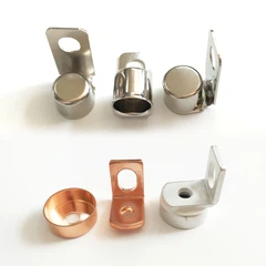
For contacts featuring a multi-layer structure, a backing substrate can be used to enhance mechanical support and thermal conductivity. For instance, steel/CuNi-backed contacts leverage the distinct properties of different materials, allowing the functional contact layer and the load-bearing substrate to handle electrical conduction, heat dissipation, and mechanical support, respectively.

Impact of contact structure on welding risk
Contact geometry determines not only the contact area but also the current density distribution, arc movement path, and heat dissipation efficiency. In high-current applications, an excessively small effective contact area can lead to current concentration, causing a rapid localized temperature rise.
Button-style contacts typically require a comprehensive design approach that considers diameter, thickness, contact pressure, and mounting method.
Bimetallic button contacts utilize a dual-metal structure to combine the functional properties of different materials, enabling optimization for both electrical conductivity and arc resistance.
To withstand higher breaking energies, trimetallic structures can further integrate the material properties of functional, conductive, and supporting layers. Trimetallic button contacts improve overall performance through the combination of distinct metal layers, though specific structural designs must still be validated against current and lifespan requirements.
The joining process between the contact and the substrate also warrants careful consideration. When using electrical contact welding to join contacts to a metal substrate, it is essential to control welding energy, pressure, interface conditions, and the heat-affected zone. This prevents connection defects from evolving into sources of localized overheating during prolonged current cycling.
High-Frequency Switching and Heat Accumulation
A contactor's operating frequency directly affects the thermal equilibrium of its contacts. With very frequent switching, contacts are subjected to current and arcing before they can fully dissipate heat; this leads to continuous heat accumulation and a steady rise in the average contact temperature.
High temperatures alter the mechanical properties, resistivity, and surface condition of contact materials. Inadequate heat dissipation can lead to further temperature rises, creating a cycle of "increased temperature rise → changes in material properties → changes in contact resistance → further heating."
Therefore, for equipment involving high-frequency operation, factors such as contact material, contact dimensions, contact pressure, heat dissipation paths, and internal thermal management within the contactor housing must all be considered. For welding equipment, automated production lines, and actuators subject to frequent start-stop cycles, lifespan and temperature rise testing should be conducted based on actual operating cycles rather than relying solely on static rated parameters.
Environmental Factors and Contact Reliability
The operating environment also impacts long-term contact reliability. Dust, oil, corrosive gases, and high humidity can alter the condition of contact surfaces. Contaminant adhesion can increase contact resistance and exacerbate localized heating, while humid environments may accelerate metal surface oxidation or corrosion.
In corrosive environments, contact materials must possess adequate environmental resistance. Additionally, the likelihood of contaminants entering the contact area should be minimized through appropriate housing protection, sealing designs, and installation methods.
For high-reliability electrical equipment, attention must also be paid to material migration, changes in surface roughness, and variations in contact resistance following long-term operation. Contact conditions should not be assessed based on appearance alone; instead, a comprehensive evaluation incorporating resistance, temperature rise, and operational performance is required.
Arc Control and Arc-Extinguishing Structures
A key strategy for reducing the risk of contact welding is controlling the arc energy generated during contact separation. The design of the arc-extinguishing system must be compatible with the contact material, load type, and operating voltage.
Magnetic blowout arc-extinguishing systems utilize magnetic fields to alter the arc's path, stretching the arc and accelerating heat dissipation to shorten its duration. Arc-extinguishing grids can split a long arc into multiple shorter arcs, thereby dispersing arc energy and enhancing the arc-extinguishing capability between contacts.
For inductive loads, appropriate surge suppression components can be incorporated into the control circuit; by limiting the rate of voltage change at the moment of disconnection, the arc energy between contacts is reduced. In practical design, the suppression method must be selected based on coil parameters, load type, and control voltage.
When contacts require a stable connection-such as through welding or brazing-processes like brazing electrical contacts require careful control of the heat-affected zone and mechanical strength at the interface to prevent the connection area from becoming a weak point during long-term operation.
Typical manifestations of contact welding faults
The most typical symptom of contact welding in a contactor is that the load remains energized even after the coil has been de-energized. If the control system has issued a disconnection command but the controlled equipment fails to stop, the main contacts should be inspected first for mechanical jamming or welding.
Upon disassembly and inspection, signs such as significant surface ablation, accumulation of molten metal, metal bridging, or abnormal pitting indicate that the contacts may have been subjected to excessive arc energy over an extended period.
For multi-pole contactors, it is also necessary to verify the consistency of contact states across different poles. Welding of a single pole can lead to three-phase load imbalance, potentially compromising the operational safety of the equipment.
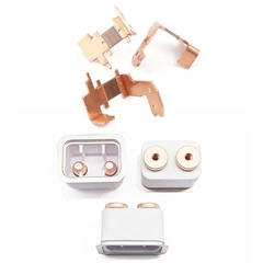
Electrical contact kits are available for the maintenance and replacement of contacts in specific equipment; however, compatibility must be verified based on the contactor model, contact specifications, and manufacturer requirements-replacement should not be based solely on physical dimensions.

Diagnosis and handling of welding faults
If contact welding is suspected, the upstream power supply must first be disconnected, and the equipment confirmed to be in a safe, de-energized state. For high-capacity equipment, manual separation of the contacts should not be attempted while the system is live.
Subsequently, the condition of the contact surfaces, the mechanical operating mechanism, and the coil control circuit should be inspected, and the actual load current measured. If issues such as overload, abnormal starting current, control signal instability, or frequent switching are present, the root cause of the fault must be investigated further.
For contacts that have undergone significant welding or severe ablation, simply grinding the surface to restore functionality is not recommended. The material microstructure, dimensions, and contact pressure of the contact surfaces may have altered; even if electrical continuity is temporarily restored, the original electrical service life may no longer be achievable.
If failures are concentrated at the interface between the contact and the base material, further inspection of the welding process, the joining interface, and mechanical integrity following thermal cycling is required to identify the root cause from both material and manufacturing perspectives.
Prevention of Contact Welding and Reliability Verification
Preventing contact welding begins with establishing appropriate parameters for product selection. Designers must consider factors such as rated voltage, rated current, actual load type, inrush current, breaking current, operating frequency, and electrical service life, rather than simply matching components based on rated current.
For applications such as new energy vehicles, energy storage systems, industrial power supplies, and DC power distribution equipment, high-current contacts require rigorous verification of breaking capacity and arc resistance. Material systems like silver-tin oxide (AgSnO2) can be employed in scenarios requiring a balance between conductivity and weld resistance, though the final material choice must be validated through service life testing under actual load conditions.
Reliability verification must encompass various operating conditions, including making (closing), steady-state current conduction, breaking (opening), repetitive operation, and abnormal load scenarios. Parameters such as contact temperature rise, contact resistance, arc duration, and surface changes should be monitored during testing to determine whether the materials and structural design meet the target service life.
For mass production, a quality control system covering contact dimensions, material composition, surface quality, joint strength, and electrical performance is essential. Process monitoring of key manufacturing parameters helps minimize performance variability caused by material fluctuations or inconsistencies in the manufacturing process.

Key Considerations for Applications in New Energy and DC Electrical Systems
With the advancement of new energy vehicles, energy storage equipment, DC charging systems, battery systems, and high-power power supplies, the operating voltage and current ratings of contactors have steadily increased. Compared to traditional low-power control circuits, these systems impose stricter requirements regarding contact breaking capacity, weld resistance, and long-term reliability.
High-voltage contactors in new energy vehicles often must handle high-current switching within limited spatial constraints; consequently, contact materials, arc-extinguishing structures, and thermal management systems require integrated design. Energy storage systems, meanwhile, may operate under high loads for extended periods and undergo frequent start-stop cycles and ambient temperature fluctuations, meaning contact service life cannot be adequately assessed through a single set of experimental conditions.
For power electronic equipment requiring high-reliability operation, contact design must be coordinated with control strategies, current sensing, pre-charge circuits, and protection systems. If the system can reduce load current or dissipate stored inductive energy before the main contacts open, the arc energy to which the contacts are subjected can be reduced at the system level.
In summary, contact welding is a failure mode resulting from the complex interplay of electrical, material, thermal, and mechanical factors; therefore, its mitigation cannot rely on any single material or structural feature alone. A robust contact reliability design must be founded on adequate current margins, matched contact materials, stable contact pressure, effective arc-extinguishing structures, reliable manufacturing processes, and a comprehensive service-life validation system.
From an engineering procurement perspective, the selection of contactors or contact assemblies should focus on verifying contact materials, base structures, joining processes, rated current, breaking capacity, operational lifespan, and actual load conditions to ensure that the supplied contact solution aligns with the electrical parameters and reliability requirements of the complete system.
contact us

Send Inquiry