










Application And Technical Essentials Of Heat-Shrinkable Insulation Materials For Copper Busbar Protection in Substations
Sep 17, 2026
Leave a message
As substation electrical equipment evolves toward higher voltages, greater integration, and more compact designs, the requirements for insulation protection on switchgear, busbars, and connection points have become increasingly stringent. During long-term operation, factors such as humidity, condensation, salt spray, industrial pollution, ice accumulation, and contact with foreign objects can compromise the insulation margin between exposed conductors and surrounding structures. For traditional bare copper busbars, design considerations must extend beyond meeting standard current-carrying and temperature-rise requirements to include phase-to-phase insulation, phase-to-ground insulation, mechanical protection, and long-term environmental adaptability.
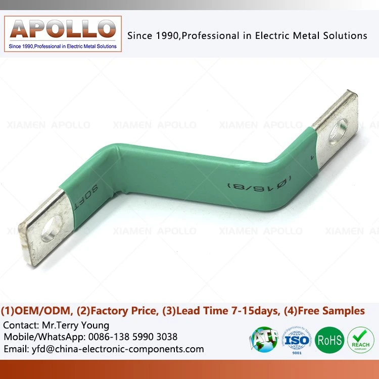
Heat-shrinkable insulation materials utilize the shape-memory properties of polymers to provide protective encapsulation. Once cross-linked, these polymer materials shrink at specific temperatures, reverting to a pre-set, stable configuration. When fabricated into tubing, tapes, or other protective structures, they can be heated to conform tightly to the conductor surface, creating a continuous insulating layer.
In substation applications, heat-shrinkable materials are commonly used for bare busbars, busbar joints, internal switchgear conductors, specialized connection points, and as supplementary protection for insulator creepage distances. Their primary function is not to alter the electrical conductivity of the copper busbar itself, but to establish a stable insulating and environmental barrier around the conductor, thereby maintaining an adequate safety margin for insulation in complex operating environments.
For power equipment requiring long-term operation, the use of heat-shrink tubing on copper busbars represents a standard insulated busbar configuration; heat-shrink tubing is applied over the copper busbar and heated to bond the insulation tightly to the conductor. Compared to simple bare copper busbar designs, this method reduces the conductor's direct exposure to humidity, salt spray, and pollutants, while minimizing the risk of direct contact between foreign objects and live components.
In terms of material composition, heat-shrink tubing typically consists of cross-linked polymers, with functional additives incorporated to meet specific electrical ratings, operating temperatures, mechanical properties, and environmental conditions. Material selection must focus on key parameters-such as dielectric strength, volume resistivity, flame retardancy, heat resistance class, aging resistance, and long-term environmental stability-rather than relying solely on initial insulation performance.
For switchgear or power distribution equipment with limited space, heat-shrink insulation helps optimize spatial utilization between conductors. By insulating copper busbars-while still meeting requirements for electrical clearance, creepage distance, and insulation coordination-the external protective space required for bare conductors can be reduced. Consequently, in compact power distribution designs, heat-shrink insulated copper busbars offer a structural solution that enhances both insulation protection and space efficiency.
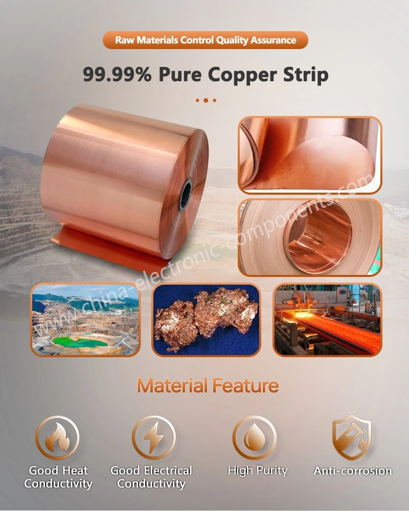
While copper busbars possess excellent electrical and thermal conductivity, their surfaces remain susceptible to oxidation or contamination when exposed over time to air, moisture, salt spray, or corrosive pollutants. Environmental factors must be factored into insulation design, particularly for electrical equipment located in coastal substations, industrial zones, or hot and humid environments. The continuous coating formed by heat-shrink material acts as a barrier against the external environment, reducing the likelihood of contaminants depositing directly onto the conductor surface.
Flat copper busbars are widely used for high-current connections in new energy power systems and energy storage equipment, where designs must simultaneously address high current-carrying capacity, limited installation space, and reliable insulation requirements. In these applications, flat copper busbars with heat-shrink tubing combine current transmission with external insulation protection, making them suitable for battery systems, power distribution modules, and other high-current electrical interconnects.
The impact of heat-shrink insulation on busbar temperature rise is a critical factor to verify during engineering design. Since the heat generated during busbar operation depends on current, resistance, and heat dissipation conditions, the addition of an insulation layer cannot be judged solely by whether the conductor is covered; instead, a comprehensive assessment is required, considering factors such as busbar cross-sectional area, operating current, ambient temperature, installation method, and the thermal properties of the insulation material.
In practical engineering, the thickness of the insulation layer, the material's thermal conductivity, and the quality of the fit against the conductor all influence heat transfer. Significant air gaps between the heat-shrink layer and the copper busbar can increase local thermal resistance, leading to localized temperature rises. Therefore, installation procedures must ensure the material shrinks fully and adheres tightly to the conductor surface, with particular attention paid to bent sections, ends, and connection points.
Insulation design for busbar connection points is typically more complex than for straight sections. Structural discontinuities and localized electric field concentrations can occur at bolted connections, welded joints, and transition zones between conductors of different cross-sections. When utilizing heat-shrink tubing for busbar connections, adequate space must be allocated for installation, maintenance, and heat dissipation based on the connection method, while ensuring the insulation layer provides continuous and reliable coverage across the connection area.
The flame-retardant performance of heat-shrink materials is a critical factor in the selection of power equipment. Substations and switchgear cabinets contain high densities of electrical energy; in the event of a fault, the insulation material must not act as a medium for rapid flame propagation. Therefore, heat-shrink materials with appropriate flame-retardant properties should be selected based on equipment ratings and relevant standards, and their performance verified through prescribed tests covering flammability, heat resistance, and electrical characteristics.
Long-term reliability is another key consideration. During prolonged operation, heat-shrink insulation materials may be subjected to the combined effects of temperature cycling, UV radiation, humidity, electric fields, mechanical vibration, and contaminants. The material's cross-linked structure, formulation, and manufacturing quality influence its long-term performance. Consequently, engineering applications should not focus solely on initial dielectric strength test results; verification through accelerated aging, thermal cycling, and environmental adaptability tests should also be conducted, taking into account the equipment's expected service life and actual operating environment.
For battery systems, power supplies, and high-current power distribution systems, designs featuring solid copper busbars with heat-shrink tubing prioritize the continuity and high conductivity of the copper conductor itself, while using the heat-shrink insulation layer to minimize the risk of conductor exposure. Such designs require determining the busbar dimensions and insulation structure based on actual current ratings, installation space, bending radii, and terminal connection methods.
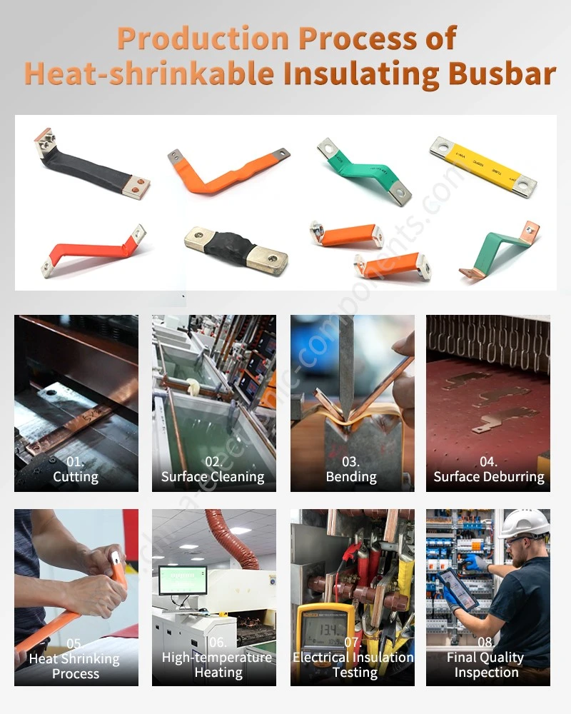
The quality of the heat-shrink tubing installation directly impacts the final insulation performance. Prior to installation, the copper busbar surface should be inspected for burrs, sharp edges, oil, and oxidation, followed by cleaning and pre-treatment in accordance with material specifications. Sharp corners should be chamfered or rounded to prevent sharp points from damaging the insulation layer during the heat-shrinking process.
Uniform heating is also essential. Excessive localized heat can cause surface overheating, discoloration, or even degradation of the insulation material's properties, whereas insufficient heat may result in incomplete shrinkage, leading to the formation of air gaps between the insulation layer and the conductor. For longer busbars, installation should proceed gradually in a logical heating sequence to ensure the heat-shrink layer contracts uniformly, thereby avoiding significant wrinkling, scorching, or areas of incomplete shrinkage.
The ends of the busbars represent another critical aspect of insulation design. The heat-shrink layer should not simply cover all connection areas without engineering assessment, as bolts, crimp terminals, and other connectors often need to remain accessible for maintenance and must meet specific requirements regarding contact resistance and heat dissipation. For locations requiring conductive contact, the termination point of the insulation layer must be determined based on the equipment structure, ensuring the insulation edge possesses sufficient mechanical strength.
In certain high-reliability electrical connection systems, a combination of tin-plated copper busbars and insulating materials is employed. Tin plating enhances the copper conductor's oxidation resistance and connection compatibility, while the heat-shrink insulation provides external protection. This type of configuration is particularly suitable for electrical components that require a balance of conductive connectivity, environmental resilience, and insulation protection.
Insulation protection must extend beyond the busbar body itself to cover connection points, bends, adjacent conductors, and areas susceptible to external contamination. Insulating only the straight sections while leaving connection ends and structural transitions largely exposed may compromise the overall effectiveness of the protection. Consequently, insulation schemes for substations should be designed with the complete electrical structure in mind, rather than merely adding a specific insulating material.
In heavily polluted operating environments, surface contaminants can combine with moisture to create conductive paths, leading to increased leakage current across the insulation surface. While heat-shrink insulation structures reduce the likelihood of contaminants depositing directly onto live copper busbars, they cannot substitute for a comprehensive external insulation design. For high-voltage equipment, factors such as air clearances, creepage distances, insulator performance, surface electric field distribution, and environmental pollution levels must all be considered.
Environments prone to condensation also require targeted design considerations. Temperature fluctuations can cause water vapor to form a film on equipment surfaces; if defects exist in the conductor or insulation structure, this film may degrade surface insulation performance. Therefore, when using heat-shrink materials in hot and humid regions, it is essential to evaluate the material's moisture absorption characteristics, sealing integrity, and long-term environmental durability.
For outdoor substations, salt spray and industrial pollution are significant factors affecting the long-term operation of busbars. Salt deposits can form a conductive pollution layer, increasing surface leakage current and the risk of flashover. While appropriate insulation coating can minimize direct contact between contaminants and the conductor, equipment intended for long-term outdoor use requires an integrated design that also addresses waterproofing, UV resistance, and mechanical protection.
Heat-shrink materials can also be used to enhance the creepage distance of certain insulator structures. By adding insulating components with a specific profile height to the insulator surface, the path of surface leakage current can be altered. However, creepage distance design must be calculated based on rated voltage, pollution levels, material pollution resistance, and specific standards; simply increasing material thickness is not a solution for all insulation issues.
Heat-shrink insulation technology offers practical advantages for the retrofitting of aging substations. Some older equipment features exposed conductors, and projects are often constrained by limited space and restricted outage windows for maintenance. During retrofitting, appropriate heat-shrink tubing, tape, or localized insulation structures can be selected based on the existing configuration, thereby minimizing the need for major structural modifications.
However, during retrofit projects, personnel must pay close attention to voltage verification, grounding, the scope of power outages, and the conditions required for insulation application. Heat-shrink materials are not a substitute for standard electrical maintenance safety protocols. Any work involving live equipment must adhere to relevant safety regulations, and insulation protection measures should only be implemented after the equipment's status has been verified.
From a product design perspective, an insulated copper busbar is far more than just a "copper bar with a plastic coating." A truly reliable solution requires the simultaneous consideration of conductor material, cross-sectional dimensions, current-carrying capacity, connection structure, insulation material, heat-shrink processing, operating temperature, environmental conditions, and the final installation method. This is particularly critical in high-voltage, high-current, and high-reliability applications, where both electrical performance and mechanical structure must be validated in tandem.
With the advancement of new energy, power electronics, energy storage systems, and compact power distribution equipment, the structural design of copper busbars is evolving from simple high-current conductors into integrated connection assemblies. Insulation coating, bending, surface treatment, and connection structures can be designed synergistically within a single component, enabling the busbar to simultaneously perform functions such as current transmission, spatial routing, and electrical isolation.
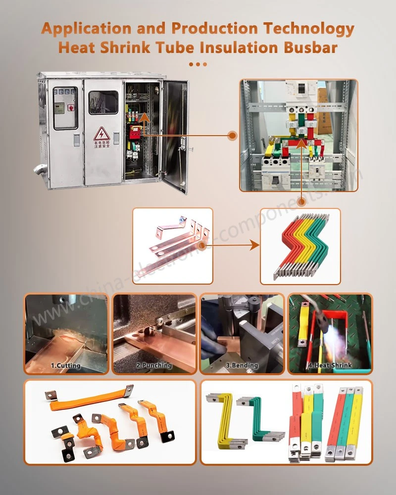
Therefore, when applying heat-shrink insulation technology in substations and related electrical equipment, a comprehensive quality control system must be established-covering everything from material selection, structural design, manufacturing, and installation to final electrical testing. Only when insulation performance, temperature rise, mechanical strength, environmental resilience, and long-term reliability all meet application requirements can heat-shrink insulated busbars truly deliver their engineering value.
For projects requiring custom heat-shrink insulated copper busbars, the procurement phase should focus on verifying key specifications-such as copper grade and cross-section, heat-shrink material grade, insulation thickness, connection method, surface treatment, operating current, and voltage rating-while also validating the structure and performance against engineering drawings and the actual installation environment.
contact us
Send Inquiry