










The Laminated Busbars in PV-plus-Storage And High-Power Power Electronic Systems: Trends in Low Stray Inductance And Reliability Design
Sep 18, 2026
Leave a message
As power electronic systems-such as those for photovoltaic power generation, energy storage inverters, electric vehicles, and rail transit-evolve toward higher power densities and higher switching frequencies, the switching speeds of power devices have increased. Consequently, the impact of internal parasitic parameters on operational performance has become increasingly significant. Against this backdrop, laminated busbars have evolved from simple connectors for power transmission into critical structural components that influence power loop inductance, voltage overshoot, thermal management, and electromagnetic compatibility (EMC).
In traditional power converters, busbars primarily serve to transmit DC power and provide electrical connections between various power units. However, when systems employ high-speed power devices such as IGBTs, SiC MOSFETs, or GaN devices, the high di/dt and dv/dt generated during switching transients amplify the effects of parasitic parameters within the power loop. If the busbar structure is poorly designed, significant loop stray inductance can lead to pronounced voltage overshoot and high-frequency oscillation during switching; this increases voltage stress on the devices and places additional demands on system EMI control.
Therefore, in high-power conversion equipment, busbar selection can no longer be based solely on current-carrying capacity; factors such as electrical topology, loop area, interlayer insulation, thermal conductivity, mechanical mounting, and high-frequency current distribution must also be considered. Low-inductance structures have become a key focus in power interconnection design, particularly for high-speed switching applications.
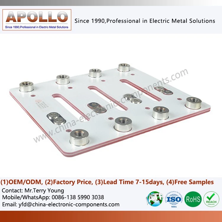
Basic Structure and Operating Principle of Laminated Busbars
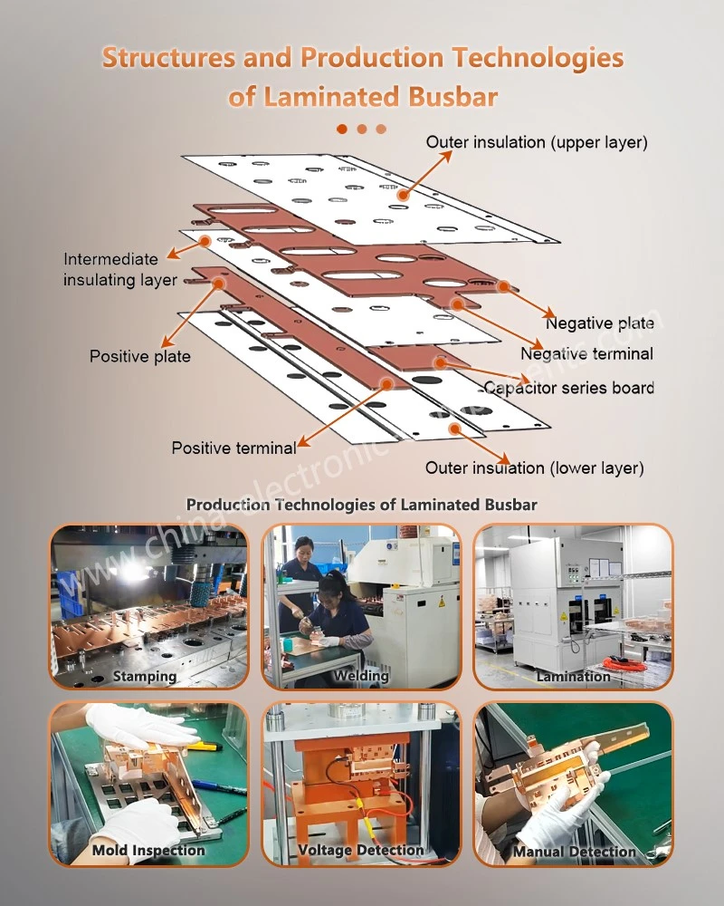
Laminated busbars are typically formed by stacking, positioning, and laminating two or more conductive metal plates with insulating dielectric layers in a specific configuration. Common conductor materials include copper and copper alloys, though materials such as aluminum may be used depending on weight, cost, and current-carrying requirements. Interlayer insulation materials must meet stringent requirements regarding dielectric strength, temperature resistance, mechanical stability, and long-term reliability.
Compared to traditional discrete copper busbars, the primary advantage of the laminated structure is its ability to position conductive paths of opposite polarity or different potentials in proximity. When currents flowing in opposite directions pass through adjacent conductors, their respective magnetic fields partially cancel each other out, thereby reducing the effective magnetic field energy and parasitic inductance of the commutation loop.
For high-power converters, this structure is particularly well-suited for minimizing the current commutation path between the DC bus and the power modules. With proper design, a busbar not only facilitates high-current transmission but also reduces the area of the high-frequency commutation loop at the structural level, thereby creating more stable operating conditions for high-speed power devices.
Busbar layer counts vary depending on the circuit topology. For instance, a two-level converter might utilize a dual-layer structure (positive and negative poles), whereas a multi-level converter may require additional layers-such as a neutral point or other potential levels-resulting in a multi-layer configuration like a three-layer laminated busbar. As the number of layers increases, issues regarding electrical isolation, parasitic parameter coupling, and thermal management become more complex; consequently, a holistic design approach tailored to the specific topology is required.
Low Stray Inductance: A Key Design Metric for High-Power Systems
Stray inductance within the power loop arises primarily from the conductors themselves, connection terminals, the internal structure of power modules, and the spatial arrangement of the busbars. Although designers do not intentionally introduce these inductances, they exert significant dynamic effects during high-speed switching operations.
Based on fundamental inductive principles, even minimal parasitic inductance can generate substantial transient voltages when the rate of current change is high. For high-speed switching devices, an excessively long commutation loop or a large separation between positive and negative current paths increases the likelihood of voltage overshoot and high-frequency ringing.
A primary focus in laminated busbar design is minimizing the distance between positive and negative current paths and shortening the connection distance between power modules and DC link capacitors. Optimizing conductor spacing reduces the area enclosed by the commutation loop, making it easier to control magnetic field coupling and loop parasitic inductance.
Therefore, when designing laminated busbars for high-power converters, engineers must consider the entire commutation loop rather than focusing solely on the busbar's dimensions. The relative positioning of capacitors, power modules, connection terminals, and busbars all influence the final loop parameters.
Simultaneous Consideration of Current Distribution and Thermal Management
Low inductance does not obviate the need for thermal design. As system power increases, the continuous current load on the busbar rises; simultaneously, high-speed switching subjects high-frequency current distribution to skin and proximity effects.
At higher frequencies, current does not remain uniformly distributed across the conductor's cross-section but tends to concentrate in specific surface areas. If the width, thickness, and interlayer spacing of the busbar are not designed optimally, issues such as localized increases in current density and concentrated temperature rises may occur.
Therefore, the design of the busbar cross-section requires balancing current-carrying capacity, AC losses, mechanical strength, and heat dissipation conditions. For high-power energy storage converters, in addition to calculating DC current-carrying capacity, it is essential to consider AC resistance variations at actual operating frequencies and verify the design through temperature rise testing.
While a laminated structure can reduce the current loop area, the multi-layer insulation structure may alter the heat dissipation path from the conductor to the exterior. Consequently, factors such as copper layer thickness, insulation material, mounting methods, and external cooling conditions must be considered during the design process. Different thermal design strategies may be required for busbar structures depending on whether the equipment utilizes natural cooling, forced-air cooling, or liquid cooling.
Connection structures are a critical factor influencing parasitic parameters
In actual systems, parasitic inductance is not confined to the main body of the busbar; significant parasitic parameters can also arise in the connection zones between the busbar and components such as power modules, capacitors, and other electrical parts.
Connection bolts, terminal transitions, localized bends, and abrupt changes in conductor cross-section can all alter the current path. If the connection point is far from the power device, the entire commutation loop may still exhibit substantial parasitic inductance, even if the main busbar employs a low-inductance laminated structure.
Therefore, engineering designs should minimize unnecessary transition structures and ensure the continuity of high-frequency current paths. For systems requiring multi-point connections, geometric symmetry among parallel branches should be maintained as much as possible to ensure similar electrical path and impedance characteristics across the branches.
Similar design principles are applied in areas such as laminated busbars for electric vehicles and high-voltage electric drive systems. As electric drive systems evolve toward higher voltages and power densities, busbars must not only meet high-current transmission requirements but also adapt to limited installation space and complex mechanical structures.
Busbar Structural Design for Complex Installation Environments
In practical industrial equipment, busbars are rarely situated in regular, open installation spaces. Strict spatial constraints imposed by power modules, capacitors, heat sinks, control boards, and structural components often necessitate busbar configurations involving bends, cutouts, branches, and multi-layer connections. For laminated busbars used in complex installations, the design focus extends beyond conductor dimensions to include alignment precision between layers, insulation boundaries, and the consistency of mounting interfaces.
Holes and cutouts in the busbar alter local current paths. If these features are located near primary commutation zones, current may be forced to divert around them, thereby affecting local current density and parasitic parameters. Consequently, the location, size, and edge treatment of openings must be evaluated during the structural design phase to prevent mechanical mounting requirements from adversely affecting electrical performance.
In high-voltage systems, electric field concentration at conductor edges and insulation interfaces must also be addressed. Proper use of radii, chamfers, and insulation encapsulation can mitigate local electric field enhancement and reduce the risk of insulation failure during long-term operation.
High-Voltage Systems Demand Rigorous Insulation Design
When DC bus voltages reach levels of several hundred volts or higher, busbar design transcends simple current transmission; it must also account for clearance, creepage distance, dielectric strength, and long-term insulation reliability.
In high-voltage inverters, the insulation material between conductor layers must withstand both continuous operating voltage and repetitive voltage stress caused by switching transients. For specialized equipment-such as high-voltage, explosion-proof inverter busbars-structural design must also align with equipment ingress protection (IP) ratings, environmental conditions, and safety standards.
Insulation material selection should factor in long-term operating temperature, dielectric strength, mechanical strength, moisture resistance, and aging characteristics. For high-frequency, high-speed switching systems, the material's long-term stability under repetitive dv/dt stress is also a critical consideration.
At the same time, simply maximizing insulation thickness is not the optimal approach. Excessively thick insulation increases the spacing between conductors, thereby enlarging the commutation loop area and potentially raising parasitic inductance. Therefore, practical design requires striking a reasonable balance between insulation safety margins and the goal of minimizing inductance.

Three-Level Topologies Drive the Evolution of Multilayer Busbars
As medium- and high-voltage power conversion equipment evolves, multilevel topologies are increasingly being adopted in energy storage converters, industrial variable-frequency drives (VFDs), and high-voltage power electronics systems. While three-level structures allow voltage stress on components to be distributed across multiple potential levels, they also introduce greater complexity to the busbar structure. When designing laminated busbars for three-level inverters, the busbar must typically manage electrical connections involving positive, neutral, and negative terminals simultaneously. Since current commutation paths may shift depending on the operating state, the busbar design cannot be optimized for a single state alone; instead, it must accommodate commutation loops across all primary switching states.
Design efforts also prioritize maintaining geometric symmetry across power branches. Significant disparities in path lengths between parallel branches can lead to uneven dynamic current distribution, causing certain components to endure higher current loads and thermal stress.
This is a key reason why multi-layer composite busbars are highly valuable in high-power equipment. By combining multiple conductor layers with insulating materials, these busbars enable compact connections involving multiple voltage potentials and branches within a limited footprint, while offering greater design flexibility regarding inductance control and mechanical layout.
Laminated Busbars and Their Applications in Power Electronics
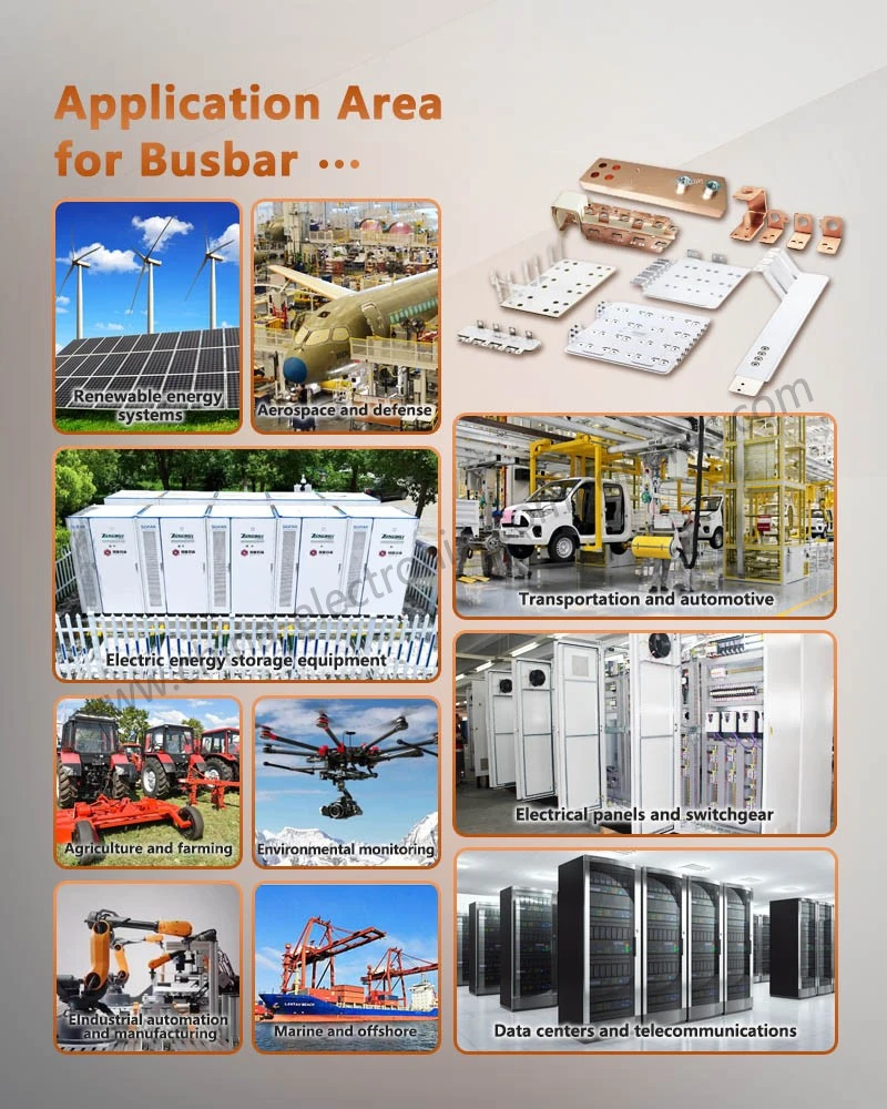
The application of laminated busbars has expanded beyond traditional industrial power supplies into sectors such as energy storage, automotive, telecommunications, computing, rail transportation, and high-end industrial machinery.
In variable frequency drives (VFDs) and motor control systems, low-inductance busbars shorten the high-frequency commutation path between power components and DC-link capacitors; consequently, laminated busbars are a standard choice for VFD architectures. For high-power motor controllers, designs must also account for high current-carrying capacity, thermal cycling, and mechanical vibration.
Data centers and high-performance computing systems often demand high power density and compact installation footprints. Busbars can be arranged in multi-layer configurations within cabinets to serve server power supplies, backplanes, and power distribution networks. In these environments, laminated busbars for supercomputer circuit boards or backplanes must balance space constraints and high current density with electromagnetic compatibility (EMC) requirements between signal and power systems.
Telecommunications infrastructure presents similar requirements. Base stations, routers, and telecom power equipment often require the interconnection of multiple power modules within limited structural space, necessitating busbar designs that facilitate modular installation and low-impedance power delivery. In such equipment, laminated busbars designed for cellular base station power distribution are used to create compact power distribution paths. For servers and communication equipment, Power Distribution Unit (PDU) busbars typically serve as centralized power distribution points for multiple load branches; their structural design must prioritize current-carrying capacity, temperature rise, insulation, and ease of maintenance.
Application Trends in New Energy Vehicles and Energy Storage Systems
New energy vehicles (NEVs) represent a key application area for high-power DC interconnect structures. As the voltage levels of electric drive systems rise and power densities increase, traditional wiring harnesses and distributed connection methods face limitations regarding space, current-carrying capacity, and thermal management.
Busbars in NEVs typically connect battery systems, inverters, motor controllers, and other high-voltage components; consequently, their structural design must simultaneously address current-carrying capacity, electrical insulation, vibration durability, and spatial layout.
Energy storage systems place greater emphasis on long-term operational reliability. Large-scale energy storage converters often handle high voltages and high currents, and busbar structures directly impact connection performance between power modules, capacitors, and other electrical units. A well-designed laminated structure enables shorter power loops within limited space and facilitates the modular installation of equipment.
For high-frequency switching power supplies and high-power conversion equipment, low-inductance designs help mitigate voltage overshoot and high-frequency oscillations caused by switching transients, thereby creating a more controlled electrical environment for the stable operation of power devices.
Applications in Rail Transit and High-Power Power Supply
Rail transit traction systems are characterized by high power, prolonged operation, and complex mechanical environments; their power interconnect structures must withstand high currents as well as continuous mechanical vibration and thermal cycling.
In these systems, laminated busbars are used for internal power connections within equipment such as traction converters and auxiliary power supplies. Beyond meeting electrical performance requirements, these busbars must account for equipment space constraints, mechanical mounting, insulation safety, and the long-term operating environment.
Similarly, busbar structures in traction and industrial converter equipment are often customized based on the positioning of power modules, capacitors, and heat dissipation components. For space-constrained equipment, multi-layer structures enhance the integration of power connections and reduce the space footprint associated with traditional cabling. Low-inductance design is shifting from the optimization of a single parameter to holistic system-level synergy.
With the increasing adoption of wide-bandgap power devices such as SiC and GaN-which enable higher switching speeds and operating frequencies-busbar design is evolving from traditional "current-carrying cross-section design" to a synergistic approach integrating electrical, thermal, mechanical, and insulation considerations.
Future busbar designs must not only minimize parasitic inductance but also manage AC losses, temperature rise, electric field distribution, and mechanical stress. Particularly in high-frequency systems, the busbar functions as an integral part of the power loop, with its geometry directly influencing the system's dynamic electrical behavior.
Simultaneously, busbar manufacturing technology is advancing toward higher levels of integration, incorporating features such as embedded capacitors, integrated sensors, complex 3D conductor structures, and precision insulation molding techniques. These technologies enable shorter power loops and improved space utilization while providing a structural foundation for equipment condition monitoring.
From an engineering perspective, the design of laminated low-inductance busbars is not merely about achieving the lowest possible inductance value; rather, it requires determining an appropriate target range based on factors such as power devices, operating voltage, switching frequency, thermal management, and insulation requirements. Only by co-designing the busbar with the entire power loop can the full potential of the laminated structure be realized in high-power power electronics systems.
Overall, laminated busbars have evolved from simple high-current connectors into critical structural components within high-power power electronics equipment. Their value lies primarily in features such as low stray inductance, compact power connections, controllable current paths, and high-voltage insulation designs. When sourcing these components, engineers should comprehensively evaluate materials, structural design, and custom manufacturing capabilities, taking into account system voltage, current, switching frequency, installation space, insulation requirements, and mass production processes.
contact us
Send Inquiry