



Expanding Applications Of Laminated Busbar Technology: Low-Inductance, High-Current-Carrying Designs Drive Upgrades in The Integration Of New Energy And Power Electronics Systems
Nov 14, 2026
Leave a message
As new energy vehicles, energy storage systems, data centers, and industrial power electronics evolve toward higher power density, greater efficiency, and increased compactness, traditional cabling and distributed copper busbar configurations are encountering challenges-such as complex wiring, significant space consumption, high parasitic inductance, and difficulties in ensuring assembly consistency. Laminated busbars, which utilize a composite design of multiple conductive layers and insulating materials, offer distinct advantages in optimizing current paths, reducing loop stray inductance, and enhancing the integration of electrical connections. Consequently, they are emerging as a critical connectivity solution for high-power electrical transmission systems.
Structural Principles and Technical Characteristics of Laminated Busbars
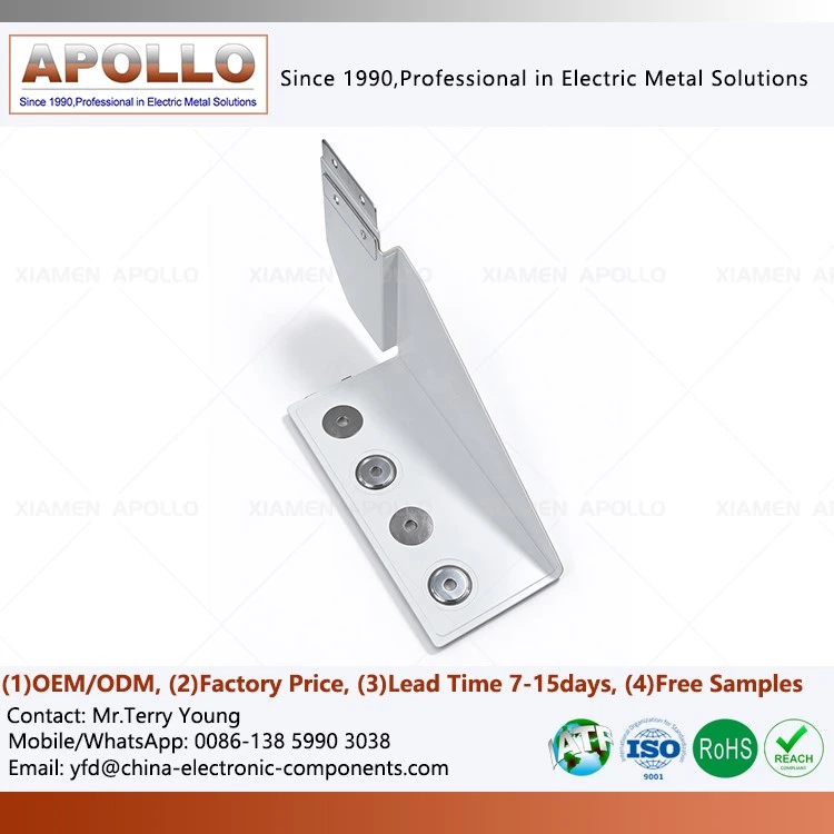
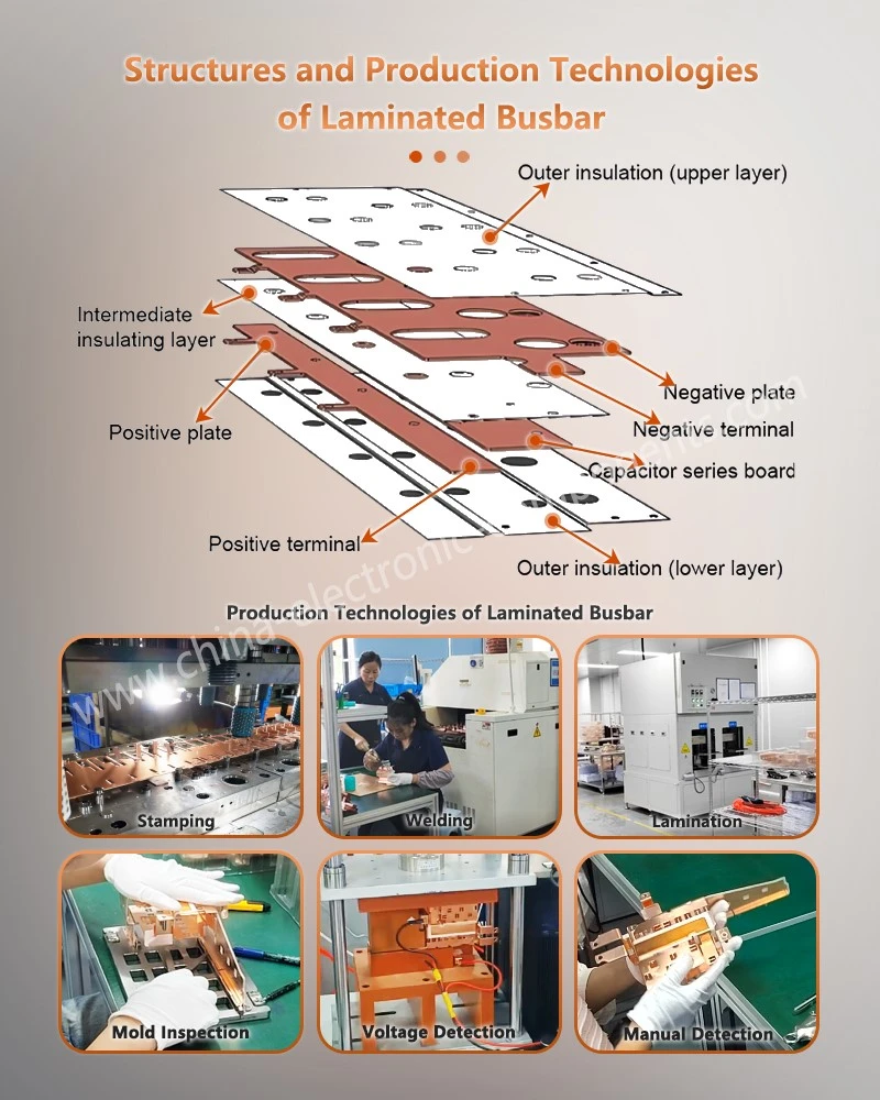
Laminated busbars-also known as composite or low-inductance busbars-typically consist of conductive layers (copper or aluminum), insulating dielectric layers, and bonding materials. Through processes such as precision machining, precise stacking, and hot-press curing, these components are integrated into a unified electrical connection assembly. Depending on the electrical topology of the equipment and the available installation space, these busbars can be designed with single- or multi-layer conductive structures. When combined with terminals, fasteners, connectors, and cables, they facilitate power transmission between power inputs, power modules, and various branch circuits.
Compared to traditional distributed busbar systems, the primary feature of a laminated structure is the parallel arrangement of conductors with opposing polarities, separated by an insulating dielectric. By creating a tightly coupled current loop between the positive and negative conductors, the loop area is minimized, which in turn reduces magnetic field coupling and stray inductance generated by current fluctuations. This characteristic is particularly vital for high-frequency switching power electronics, as it helps mitigate voltage spikes and electromagnetic interference (EMI) during the switching process.
From the perspective of system integration, laminated busbars consolidate multiple electrical connection points into a compact structure, reducing the need for complex cable routing and scattered connections, thereby simplifying assembly. For high-power-density equipment, an optimized busbar design improves internal space utilization and provides clear, efficient connection paths for power modules, filtering components, and control units.
It should be noted, however, that "low inductance" does not imply that all laminated busbars exhibit identical electrical performance. Actual performance is influenced by factors such as conductor spacing, lamination sequence, loop area, terminal structure, connection methods, and operating frequency; therefore, design and verification must be conducted in the context of the specific circuit topology.
Applications of Laminated Busbars in New Energy and Power Electronics
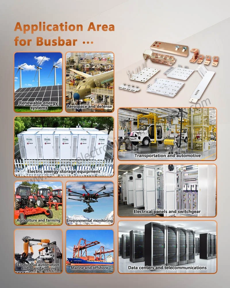
As power conversion equipment increasingly trends toward modularity and high integration, the application scope of laminated busbars has expanded from traditional industrial power supplies to sectors including new energy vehicles, renewable energy, telecommunications equipment, rail transit, and data centers. Different applications impose varying requirements on current-carrying capacity, insulation performance, mechanical strength, and installation dimensions, necessitating designs tailored to the specific equipment structure.
In the new energy vehicle sector, laminated busbars are utilized in motor controllers, traction battery systems, and high-voltage power distribution units (PDUs), facilitating power transmission between the battery and inverter modules, power devices, and other high-voltage components. For motor controller busbars, design priorities typically include rated current, loop inductance, the reliability of terminal connections, insulation spacing, and mechanical stability under vibration. An optimized lamination layout can shorten power loops and help manage parasitic parameters during switching transients.
In energy storage and renewable energy generation, photovoltaic inverters, wind power converters, and energy storage converters all involve high-current DC and AC power conversion. Laminated busbars allow for the integration of DC bus connections based on the layout of power modules, overcoming the spatial constraints associated with traditional cabling. For power distribution unit (PDU) busbars, the conductor cross-section and connection configuration must be determined based on input/output circuits, the number of branches, and the placement of protective devices-balancing current-carrying capacity, temperature rise control, and ease of maintenance.
In uninterruptible power supply (UPS) systems, power modules must ensure stable power conversion and distribution across various operating states.
UPS busbars are used in power connection structures for rectification, inversion, and DC bus circuits. Their design must account for continuous operating current, short-term overload capacity, insulation withstand voltage, temperature rise, and internal thermal conditions within the equipment, ensuring that excessive local connection resistance does not lead to abnormal heating.
Higher Demands on Busbar Integration in Data Centers and Communication Equipment
The advancement of artificial intelligence (AI) computing, high-performance servers, and cloud computing infrastructure has driven continuous upgrades to power supply architectures within data centers. As the power density of server racks increases, power distribution systems must not only accommodate higher current requirements but also optimize space utilization, connection reliability, and maintenance efficiency.
In high-performance computing equipment, laminated busbars-used for supercomputer circuit boards or backplanes-enable the construction of compact power connection structures tailored to the layout of backplanes and power modules. By optimizing the relative positioning of conductor layers, the power supply path can be shortened, while the space consumed by complex wiring harnesses is significantly reduced.
For equipment utilizing centralized power architectures, laminated busbars for power distribution backplanes can route power inputs to various functional modules, simplifying electrical connections within the backplane. Similar designs are applied in network communication equipment; for instance, laminated busbars for router backplanes can be customized based on the structural dimensions, power interfaces, and branch distribution of the router's backplane.
Communication infrastructure also places high demands on the stability and compactness of power distribution. Laminated busbars for cellular base station power distribution are used for high-current connections and distribution within base station power systems, while those designed for general telecom power distribution are tailored to specific power ratings, installation space constraints, and connection topologies. In these applications, factors such as conductor cross-section, insulation materials, connection terminals, and thermal management must be considered in an integrated manner to ensure reliable long-term operation.
As data center power systems evolve toward modularity and higher power density, busbars are no longer viewed merely as simple conductive components; rather, they have become critical elements of the overall power architecture. Solutions such as laminated busbars for internet router backplanes require precise engineering to align with equipment backplane dimensions, supply voltages, current distribution paths, and installation interfaces.
Expanded Applications in Rail Transit and Specialized Industrial Equipment
Beyond the sectors of new energy vehicles and data centers, laminated busbars are also utilized in areas such as traction converters for rail transit, high-power industrial power supplies, servo drives, and stage lighting equipment. These devices typically have high power conversion requirements; some applications must also withstand operational conditions such as continuous vibration, temperature fluctuations, and frequent start-stop cycles.
In the rail transit sector, power modules within traction converters rely on busbars for electrical power transmission and circuit interconnection.
Composite busbars for four-quadrant power modules in train power supply systems can be custom-designed based on the electrical architecture and available installation space of the modules. During the engineering development phase, critical factors-such as conductor connection points, insulation structure, mechanical fastening methods, and connection stability under vibration-must be evaluated to ensure a precise fit between the busbar and the power module.
In industrial equipment, laminated busbars are used in high-power supply units, frequency converters, and servo drive systems, helping to reduce the wiring complexity associated with discrete, point-to-point connections. For equipment with limited space and a centralized arrangement of power modules, the use of composite busbars helps optimize the internal connection architecture.
Furthermore, certain stage lighting systems and professional lighting equipment also require stable power distribution structures. Laminated busbars can be designed to accommodate the specific layout of internal power modules, control units, and lighting loads. In practical applications, the busbar structure should be determined based on the equipment's power requirements, operating environment, and insulation specifications, rather than relying solely on compact dimensions as the primary design criterion.
Key Manufacturing Processes and Quality Control for Laminated Busbars
The manufacturing of laminated busbars involves several stages, including precision conductor machining, insulation material processing, interlayer positioning, thermal-pressure lamination, and final inspection. Variations in process parameters directly affect product dimensional consistency, insulation reliability, and long-term operational stability.
The first step is the pre-processing of conductor materials. Based on the product's rated current, structural strength, electrical conductivity, and cost requirements, appropriate copper or aluminum materials are selected and subjected to cutting, punching, bending, and surface treatment. Common conductor materials include electrolytic tough-pitch (ETP) copper, oxygen-free copper, and specific aluminum alloys tailored for particular applications.
Terminal contact areas may be finished with tin plating, silver plating, or other suitable coatings to enhance the performance of the contact interface and mitigate the effects of oxidation.
The second step involves the processing of insulation materials and the precise positioning of the layers. For the insulating medium, materials such as polyimide film, epoxy-based insulation, or other suitable systems may be selected based on operating voltage, temperature resistance rating, dielectric properties, and mechanical requirements. During processing, it is essential to control the dimensions, aperture positioning, and edge integrity of the insulating layers, while ensuring that the conductors and insulating layers are arranged in the sequence specified by the design. Positioning jigs and tooling are used to manage the relative alignment of the layers, preventing conductor misalignment that could compromise insulation distances or assembly precision.
The third step involves hot-press lamination and curing. This process requires the determination of specific temperature, pressure, duration, and curing conditions tailored to the chosen insulating materials and adhesive systems. In vacuum hot-pressing, the vacuum environment helps minimize residual air and bubbles between layers; however, the final quality remains dependent on the material system, process parameters, and rigorous process control. Following hot-pressing, the inter-layer bonding, edge condition, and overall structural dimensions must be inspected to ensure the absence of delamination, air bubbles, or localized poor adhesion.
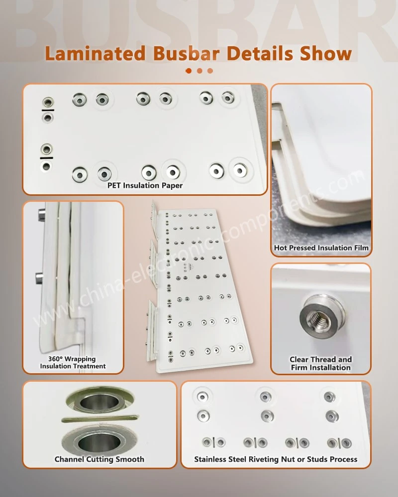
The fourth step consists of post-processing and terminal treatment. This includes contour cutting, terminal processing, connector assembly, and any necessary soldering, all performed in accordance with product drawings. For structures requiring edge sealing or protective treatment, appropriate techniques-such as edge sealing, potting, or the application of insulating protective coatings-may be employed based on the product's intended operating environment. Once processing is complete, the component should be deburred, and its hole positions, external dimensions, flatness, and connection interfaces must be verified to ensure precise assembly with the target equipment.
Key Factors in Laminated Busbar Selection and Engineering Validation
A laminated busbar is more than just a simple stack of copper conductors and insulating films; its design requires a comprehensive evaluation across multiple dimensions, including electrical, thermal, and mechanical performance, as well as manufacturing feasibility.
First, the conductor material and cross-sectional area must be determined based on continuous operating current, peak current, operating voltage, and load fluctuations. The conductor cross-section influences not only electrical resistance and current-carrying capacity but also temperature rise and the overall dimensions of the component. For high-frequency switching circuits, particular attention must be paid to the arrangement of positive and negative conductors and the resulting loop inductance; where necessary, design outcomes should be verified through simulation and testing.
Furthermore, the selection of insulating materials and the design of insulation structures must be determined based on operating voltage, ambient temperature, pollution degree, and the available internal space within the equipment. Electrical clearances and creepage distances-both between conductors and between conductors and the enclosure-must comply with applicable design standards and equipment requirements; safety cannot be assessed solely based on the thickness of the insulating material.
Additionally, the structure of connection terminals, the fastening methods employed, and the quality of contact surfaces are equally critical. Excessive contact resistance can lead to localized temperature increases; therefore, terminal connection structures, tightening torques, and contact interfaces must be carefully engineered. For equipment subject to vibration or thermal cycling, the mechanical stability and long-term reliability of these connections must also be evaluated.
Finally, the manufacturing process requires a robust quality inspection system. This includes verifying conductor dimensions, hole positioning and overall geometry, performing dielectric withstand (hipot) and insulation resistance tests, conducting continuity checks, and carrying out necessary temperature-rise verification. For products with complex structures or stringent application requirements, further validation-such as assessing interlayer bonding quality, connection strength, and environmental adaptability-may be conducted in accordance with the client's technical specifications.
Customized Laminated Busbars: A Key Development Trend in Power Connection Systems
Driven by the ongoing evolution of new energy vehicles, energy storage systems, telecommunications infrastructure, and high-performance computing equipment, power connection systems are trending toward higher integration, lower parasitic parameters, reduced weight, and modularity. By utilizing a composite structure of conductors and insulating layers, laminated busbars offer a more centralized solution for high-current transmission within equipment. Their value lies not only in reducing cabling and optimizing spatial layout but also in providing systematic management of electrical connection paths and ensuring manufacturing consistency.
For engineering procurement and R&D teams, the selection of a laminated busbar supplier should focus on key capabilities: material selection, precision stamping and bending, insulation lamination processes, terminal welding quality, dimensional control, and electrical testing proficiency.
Moreover, product design requirements-including current, voltage, installation space, connection interfaces, insulation specifications, and operating environment-should be clearly defined during the early stages of development to minimize the risk of subsequent structural modifications or assembly compatibility issues. To meet the application requirements of new energy vehicles, power electronics, energy storage systems, and industrial equipment, Apollo provides comprehensive support-including the processing of copper and aluminum busbars, integration of insulating materials, precision stamping, bending, and the fabrication of connection components.
Engineering and procurement teams may submit product drawings, 3D models, or preliminary technical specifications-along with details such as rated current, operating voltage, conductor material, insulation requirements, and application context-to facilitate the assessment of structural feasibility, manufacturing processes, sample validation protocols, and mass production requirements. This ensures the successful implementation of laminated busbars, from initial design and development through to stable, full-scale production.
contact us

Send Inquiry