










Quality Control for Silver Contact Assemblies: ±0.01 mm, IATF 16949 and PPAP Level 3
Sep 05, 2026
Leave a message
Automated silver contact riveting and welding assemblies require controlled contact geometry, joint strength, plating integrity and electrical resistance-not visual inspection alone. For high-volume relay, contactor, circuit breaker and fuse applications, the production target should be a traceable process window covering dimensional tolerance, riveting force, weld energy, shear strength, metallographic structure and surface condition.
For a riveting contact assembly supplier, the main quality risk is not simply whether the silver contact is attached. The engineering question is whether the joint remains mechanically stable and electrically conductive after millions of switching cycles, thermal excursions and vibration loads.

±0.01 mm Contact Geometry and IATF 16949 Process Control
Silver contact assemblies normally combine a contact rivet or contact pellet with a conductive carrier such as copper, copper alloy or nickel-plated steel. The finished assembly may be used in electromagnetic relays, AC/DC contactors, circuit breakers, automotive electrical modules and other switching devices.
The dimensional relationship between the contact and carrier directly affects electrical performance and mechanical reliability.
±0.01 mm Rivet Position and Contact Height
Typical critical-to-quality dimensions include:
Rivet position tolerance: controlled to approximately ±0.01–0.03 mm where the downstream mechanism requires tight alignment.
Contact height: controlled according to actuator travel and contact pressure requirements.
Rivet head diameter: controlled to maintain sufficient mechanical retention without excessive deformation.
Carrier flatness: controlled to prevent uneven contact pressure.
Contact concentricity: monitored when the contact surface must align with a mating contact.
Burr height: minimized to prevent interference with insulation, housing, or moving mechanisms.
For automotive programs, dimensional characteristics should be linked to PFMEA, Control Plan, work instructions, and inspection records under an IATF 16949 quality-management framework.
C1100 Copper vs. C2680 Brass for Contact Carriers
Material selection changes conductivity, formability, hardness, and riveting behavior.
| Property | C1100 Pure Copper | C2680 Brass |
| Copper content | ≥99.90% Cu typical | Cu-Zn alloy |
| Electrical conductivity | High, commonly around 100% IACS for annealed material | Lower than pure copper |
| Formability | Excellent | Good |
| Riveting deformation | Relatively easy | Higher forming resistance |
| Spring characteristics | Moderate | Better for selected geometries |
| Typical application | High-current conductive carriers | Terminals, carriers, formed electrical parts |
| Main process concern | Work hardening and deformation | Hardness variation and crackin |
The carrier material should be selected together with the contact material and joining process. A high-conductivity C1100 carrier may be preferred where current density and thermal dissipation dominate. C2680 can be advantageous where forming strength and dimensional stability are more important.
In-Die Riveting vs. Resistance and Ultrasonic Welding: Joint Integrity
The joining process determines the final contact interface. For automated production, in-die riveting electrical contacts provides a different control mechanism from resistance welding or ultrasonic welding.
In-Die Riveting for High-Volume Electrical Contacts
In-die riveting integrates contact feeding, carrier forming, piercing, riveting, and dimensional forming within a progressive die.
A typical sequence is:
Carrier strip feeding.
Pilot positioning.
Piercing or pre-forming.
Contact feeding.
Contact insertion.
In-die riveting.
Head forming.
Carrier forming.
Dimensional verification.
Part separation or reel-to-reel output.
The primary process variables include:
Feed pitch.
Contact orientation.
Rivet shank diameter.
Punch penetration.
Riveting force.
Die clearance.
Material hardness.
Head diameter.
Rivet upset height.
Carrier thickness.
The major advantage is process synchronization. The carrier and contact are positioned by the same die system, reducing manual handling and minimizing positional variation.
Resistance Welding: Current, Pressure and Time
Resistance welding generates localized heat at the joint interface through electrical resistance.
The basic process window is controlled through:
Welding current.
Weld time.
Electrode force.
Electrode geometry.
Contact resistance.
Surface condition.
Material thickness.
Insufficient energy can result in incomplete bonding or low shear strength. Excessive energy can produce expulsion, indentation, excessive heat-affected zones, or silver material deformation.
For a silver contact welding assembly, current and force should be monitored continuously rather than relying only on destructive sampling.
Ultrasonic Welding: High-Frequency Mechanical Energy
Ultrasonic joining uses high-frequency mechanical vibration to generate localized interfacial friction and bonding.
The relevant variables include:
Frequency.
Amplitude.
Weld force.
Weld time.
Energy.
Tool geometry.
Material hardness.
Surface condition.
Ultrasonic welding can be useful for specific conductive-material combinations, but the tooling interface and process window must be validated against the actual contact geometry.
Joining Process Comparison Under ISO 9001 and IATF 16949
| Parameter | In-Die Riveting | Resistance Welding | Ultrasonic Welding |
| Primary joining mechanism | Mechanical deformation | Joule heating | High-frequency vibration |
| Typical production mode | Progressive stamping | Automated cell | Automated cell |
| Contact positioning | Integrated in die | Fixture-controlled | Fixture-controlled |
| Heat input | Very low | Localized thermal input | Low bulk thermal input |
| Dimensional repeatability | High when die is stable | Dependent on fixture/electrodes | Dependent on tooling |
| Tool wear | Punch/die wear | Electrode wear | Horn/tool wear |
| Inline monitoring | Force/displacement | Current/voltage/force | Energy/amplitude/force |
| Destructive validation | Shear/pull/metallography | Peel/shear/metallography | Pull/shear/metallography |
| Best fit | High-volume riveted contacts | Welded contact assembly | Selected dissimilar-material joints |
The correct process is determined by contact geometry, carrier material, current rating, required joint strength, production volume and downstream assembly requirements.
Defect Modes in Automated Riveting and Welding
Common failure modes include:
Contact misfeed.
Contact rotation.
Incomplete rivet upset.
Excessive rivet head deformation.
Cracked carrier around the pierced hole.
Insufficient weld nugget.
Weld expulsion.
Excessive electrode indentation.
Surface contamination.
Silver layer damage.
Excessive burr formation.
Contact height out of tolerance.
Joint resistance above specification.
Each defect should be connected to a specific detection method rather than controlled through general visual inspection.

≥Specified Shear Strength, Metallography and CMM Inspection
Mechanical retention and electrical performance must be verified independently. A contact can pass a visual inspection while still having insufficient joint strength or an internal metallurgical defect.
Shear and Pull Testing for Riveted Contacts
For riveted assemblies, shear or pull testing verifies the mechanical integrity of the contact-to-carrier joint.
A controlled test plan should define:
Test direction.
Fixture geometry.
Loading speed.
Sample quantity.
Minimum acceptance force.
Failure mode.
Sampling frequency.
Lot traceability.
The numerical acceptance value must be established from the customer's drawing, application load and validation data rather than using a universal value for every contact geometry.
For production qualification, record both the measured force and failure mode. A high force value with carrier tearing is materially different from a low force value caused by contact pull-out.
Metallographic Cross-Section Analysis
Metallographic analysis exposes defects that cannot be detected from the external surface.
The standard sectioning workflow includes:
Sample identification.
Precision cutting.
Mounting.
Grinding.
Polishing.
Etching when applicable.
Optical microscopy.
Joint geometry measurement.
Defect classification.
For riveted contacts, the cross-section should verify:
Rivet penetration.
Material deformation.
Contact seating.
Cracks.
Voids.
Burrs.
Local thinning.
Carrier deformation.
Interface condition.
For welded assemblies, metallography should evaluate:
Weld nugget geometry.
Fusion zone.
Heat-affected zone.
Interface bonding.
Cracks.
Porosity.
Expulsion.
Excessive penetration.
CMM Inspection for ±0.01 mm Critical Dimensions
A coordinate measuring machine (CMM) provides dimensional verification for complex contact assemblies.
Typical CMM characteristics include:
Contact center position.
Contact height.
Rivet head diameter.
Carrier hole location.
Overall profile.
Flatness.
Parallelism.
Perpendicularity.
Datum-to-feature distance.
For high-volume programs, CMM inspection should normally be combined with dedicated gauges or automated vision inspection. CMM is highly effective for capability validation and periodic verification but is not necessarily the fastest method for 100% production inspection.
A typical quality structure is:
CMM → process capability validation → gauge correlation → inline inspection → SPC monitoring.
SPC and Cpk ≥1.33 for Production Stability
For critical dimensions, statistical process control should monitor the relationship between the specification limits and actual process distribution.
Where the customer specification permits, a commonly applied target is:
Cpk ≥1.33: stable production capability.
Cpk ≥1.67: stronger capability target for selected critical characteristics.
100% inspection: applied where failure consequences or customer requirements justify it.
The exact target should be defined by the customer quality agreement and control plan.
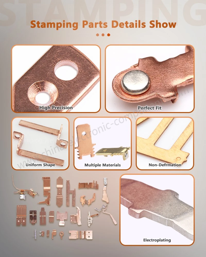
3–5 μm Plating Control, Surface Cleanliness and Electrical Resistance
Silver contacts may use pure silver, silver alloys or silver-based contact materials depending on switching current, voltage, contact welding resistance and environmental conditions.
The contact surface must be evaluated separately from the mechanical joint.
Silver Plating Thickness: 3–5 μm and Beyond
Where silver plating is specified, thickness must be measured using a method appropriate to the substrate and geometry.
Potential methods include:
X-ray fluorescence (XRF).
Metallographic cross-section.
Coulometric measurement.
Other validated coating-thickness methods.
For a specified 3–5 μm silver plating thickness, inspection should confirm both minimum thickness and local uniformity. Measuring only a flat reference surface can miss thin regions on formed edges or recessed geometries.
Contact Resistance and Current-Carrying Performance
Contact resistance is affected by:
Contact material.
Contact force.
Surface roughness.
Oxide or contamination layer.
Plating thickness.
Contact geometry.
Riveting quality.
Weld quality.
Measurement current.
Temperature.
The test method must define the measurement current, probe configuration, contact force, and stabilization time. Otherwise, resistance results from different laboratories or production lines may not be directly comparable.
Surface Cleanliness After Stamping and Joining
Stamping lubricants, oxide residues, metal particles and welding debris can affect contact resistance and downstream assembly.
Process controls may include:
Controlled stamping lubricant application.
Ultrasonic or aqueous cleaning where required.
Filtered compressed air.
Particle control.
Visual inspection under defined illumination.
Surface-residue testing where specified.
Packaging immediately after final inspection.
For high-voltage contactor applications, cleanliness requirements should be connected to insulation distance, creepage requirements, and final electrical testing.
Automated Inspection with 100% Traceability and SPC
Automation reduces operator-dependent variation, but automation itself does not guarantee quality. The control architecture must identify the physical variables that directly affect the finished assembly.
100% Vision Inspection for Contact Position and Surface Defects
Machine vision can inspect:
Contact presence.
Contact orientation.
Contact position.
Rivet head geometry.
Missing components.
Surface scratches.
Severe burrs.
Welding discoloration.
Foreign particles.
Dimensional features measurable by calibrated imaging.
Vision inspection should be validated against known-good and known-defective samples. False acceptance and false rejection rates should be tracked during system validation.
Inline Force-Displacement Monitoring During In-Die Riveting
For automated riveting, force-displacement curves provide direct information about the forming process.
Abnormal curves may indicate:
Missing contact.
Double contact.
Incorrect material thickness.
Tool wear.
Misalignment.
Excessive burr.
Material hardness variation.
Incomplete riveting.
A simple pass/fail force limit is less informative than a monitored force-displacement signature because the curve contains information about the forming sequence.
Weld Current and Energy Monitoring
Automated resistance welding should record process parameters such as:
Welding current.
Voltage.
Weld time.
Electrode force.
Dynamic resistance where available.
Energy input.
Electrode condition.
Trend analysis can identify electrode degradation before the finished product reaches a failure condition.
For production validation, destructive shear or metallographic testing should be correlated with the monitored electrical parameters.
Automated Sorting and Lot Traceability
A production traceability system should connect:
Raw material lot → stamping coil → progressive die → contact material lot → joining parameters → inspection result → operator/equipment → finished-product lot.
For Tier 1 automotive supply, the data structure should support PPAP documentation, process-change records, nonconformance analysis and corrective action.
A PPAP Level 3 submission may include, according to customer requirements:
Design records.
Engineering change documents.
DFMEA.
Process flow diagram.
PFMEA.
Control Plan.
MSA.
Dimensional results.
Material/performance test results.
Initial process studies.
Qualified laboratory documentation.
Appearance approval where applicable.
Sample production parts.
Master sample.
Checking aids.
Customer-specific requirements.
Part Submission Warrant.
IATF 16949, MSA and PPAP Level 3 Quality Documentation
A reliable supplier quality system is built around evidence rather than declarations.
MSA for ±0.01 mm Measurements
When a dimensional characteristic is controlled at the ±0.01 mm level, the measurement system must be capable of resolving and reproducing the required variation.
Typical MSA activities include:
Gauge R&R.
Bias study.
Linearity study.
Stability study where applicable.
Calibration traceability.
A measurement system with excessive variation can make a stable process appear unstable or allow defective parts to pass inspection.
PFMEA-to-Control-Plan Linkage
The PFMEA should identify the relationship between:
Failure Mode → Cause → Prevention Control → Detection Control → Reaction Plan.
For example:
| Failure Mode | Potential Cause | Prevention | Detection |
| Contact missing | Feeder malfunction | Sensor/interlock | 100% vision |
| Contact misalignment | Feed-position variation | Servo positioning | Vision/CMM |
| Low rivet strength | Incorrect forming stroke | Force-displacement control | Shear test |
| Weld nugget too small | Low current/electrode wear | Current monitoring | Destructive weld test |
| Silver coating below specification | Plating process variation | Supplier process control | XRF |
| Burr above specification | Die wear | Preventive die maintenance | Vision/gauge |
| High contact resistance | Contamination/interface defect | Cleaning control | Electrical resistance test |
This linkage makes corrective action faster because each failure mode has a predefined detection and reaction method.
Progressive Die Life, Tool Wear and ±0.01 mm Repeatability
Progressive stamping tools are production assets that directly influence contact geometry.
Tool Wear Monitoring Under High-Volume Production
Critical wear locations include:
Piercing punches.
Forming punches.
Riveting punches.
Die inserts.
Pilot pins.
Stripper plates.
Contact positioning components.
Tool maintenance intervals should be based on production shots, dimensional trend data, and actual wear rather than an arbitrary calendar schedule.
When a rivet head diameter or contact height begins drifting toward its specification limit, preventive maintenance should be triggered before the part reaches an out-of-specification condition.
Tool Qualification Before Mass Production
Tool validation should include:
First-off dimensional inspection.
Capability study.
Progressive die alignment verification.
Contact feeding validation.
Riveting force validation.
Burr inspection.
Material springback evaluation.
Trial production.
Tool wear baseline establishment.
A stable tool should produce a measurable process distribution rather than simply passing several initial samples.
ISO 14001, RoHS and REACH Material Compliance
Electrical contact assemblies often enter automotive, energy-storage and industrial electrical supply chains, making material documentation part of supplier qualification.
RoHS and REACH Documentation
Material compliance documentation should identify:
Contact alloy.
Carrier alloy.
Plating material.
Base-metal coating.
Welding consumables where applicable.
Cleaning chemicals where relevant.
Packaging materials.
Supplier declarations should be traceable to the actual material grade and production lot.
ISO 14001 and Process Chemical Control
Where stamping lubricants, plating processes, cleaning agents or welding consumables are involved, environmental controls should cover:
Chemical identification.
Storage.
Usage records.
Waste handling.
Supplier documentation.
Applicable regulatory requirements.
An ISO 14001 environmental-management system can provide the framework for controlling these processes, while product compliance remains dependent on the actual material and chemical composition.
Qualification Matrix for Automated Silver Contact Assemblies
The following matrix provides a practical quality-control structure for engineering validation and mass-production approval.
| Quality Characteristic | Inspection Method | Typical Frequency | Engineering Purpose |
| Contact position | Vision / CMM | 100% vision + periodic CMM | Assembly alignment |
| Contact height | Gauge / CMM | Inline / sampling | Actuation compatibility |
| Rivet head diameter | Vision/gauge | Inline / sampling | Mechanical retention |
| Riveting force | Force sensor | 100% process monitoring | Joint consistency |
| Joint strength | Shear/pull test | Lot/sample | Mechanical validation |
| Weld energy | Electrical monitoring | 100% | Process stability |
| Weld strength | Shear/peel test | Lot/sample | Joint validation |
| Joint structure | Metallography | Qualification / periodic | Internal defect detection |
| Silver thickness | XRF / cross-section | Lot/sample | Coating compliance |
| Contact resistance | Electrical test | According to control plan | Electrical performance |
| Burr height | Vision/microscope | Inline / sampling | Assembly safety |
| Material composition | Supplier certificate/laboratory | Incoming / lot | Material verification |
| Process capability | SPC / Cpk | Launch and ongoing | Production stability |
Supplier Selection: What a Tier 1 Buyer Should Request
A qualified riveting contact assembly supplier should be evaluated using measurable manufacturing evidence rather than equipment lists alone.
Request ±0.01 mm Dimensional Capability Data
Ask for actual capability data covering the CTQ dimensions on the drawing.
The supplier should be able to provide:
Measurement method.
Gauge resolution.
MSA results.
Cpk/Ppk data.
Inspection frequency.
Calibration status.
Reaction plan.
Request Joint-Strength and Metallography Records
For riveted or welded contacts, request:
Shear or pull-test records.
Cross-sectional photographs.
Joint dimensions.
Failure-mode classification.
Process parameters.
Sampling frequency.
This evidence is more useful than a statement that the assembly has been "tested."
Request PPAP Level 3 Capability
For automotive applications, establish PPAP requirements before tooling begins.
The supplier should confirm responsibility for:
DFM review.
Tool design.
Process flow.
PFMEA.
Control Plan.
MSA.
Dimensional inspection.
Material certification.
Performance testing.
Initial capability.
Sample submission.
Engineering-change control.
A supplier capable of providing these documents before SOP reduces the risk of discovering process-control gaps during customer approval.

Engineering Conclusion: Control the Joint, Not Just the Finished Part
The quality of an automated silver contact assembly is determined by a chain of controlled variables: material hardness, contact geometry, riveting force, weld energy, tool condition, surface cleanliness, plating thickness and measurement-system capability.
For high-volume EV, relay, contactor and industrial switching applications, the strongest production model combines in-die riveting or controlled welding, 100% automated inspection where justified, CMM verification, metallographic validation, shear testing, SPC, MSA and PPAP Level 3 documentation.
The supplier selection decision should therefore be based on demonstrated process capability and traceability. A stable ±0.01 mm dimensional process, verified joint strength, controlled 3–5 μm plating where specified, and documented IATF 16949 quality procedures provide measurable evidence for production approval.
FAQ - PPAP Level 3, T1 Sampling and Contact Plating
How long does PPAP Level 3 documentation take for an automated silver contact assembly?
A typical PPAP Level 3 package is prepared after tooling and process validation. Timing depends on drawing complexity, tool development, capability studies, MSA, material testing, and customer-specific requirements. The exact schedule should be agreed before T0 tooling release.
What is a typical T1 sample lead time for in-die riveting electrical contacts?
T1 timing depends on progressive-die complexity, contact geometry, and material availability. A new stamped contact program commonly requires tooling development followed by trial production and dimensional validation before T1 samples are released.
How is 3–5 μm silver plating thickness verified on electrical contacts?
Silver plating thickness can be verified using XRF, metallographic cross-section, or another validated coating-thickness method. Measurement locations should represent functional contact surfaces, edges, and formed areas rather than relying on one flat reference point.
contact us
\

Send Inquiry