




Magnetic Circuit Optimization: Relay Pole Shoes and Yoke Geometry for Low-Power DC Contactors
Oct 28, 2026
Leave a message
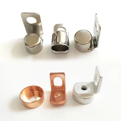
A low-power DC contactor targeting holding power below 0.5 W requires coordinated control of magnetic air gap, pole shoe geometry, yoke cross-section, and armature contact flatness. For smart meters and industrial controllers, reducing magnetic reluctance at the closed position helps maintain armature holding force with lower coil current, provided the magnetic circuit avoids saturation and the return spring remains within its specified force range. Xiamen Apollo Electronic Components (Xiamen) Co., Ltd. manufactures precision stamped relay cores, pole shoes, yokes, and armature components for electromagnetic switching assemblies.

Magnetic Circuit Design for DC Contactors with Holding Power Below 0.5 W
Magnetic Reluctance and Holding Force in a Low-Power Relay
The magnetic circuit converts coil ampere-turns into flux that attracts the armature toward the fixed iron core. Its performance depends on the coil's magnetomotive force, the effective air gap, the magnetic permeability of the iron components, and leakage flux.
This approximation assumes a reasonably uniform flux density and neglects fringing, leakage, and complex pole geometry. Actual contactor force must be verified against the complete magnetic circuit and armature mechanics.
Electrical Power and Holding-Current Requirements
For a DC coil operating at a stable voltage:
A 24 V DC coil operating at 0.5 W would draw approximately 20.8 mA at that operating point. This is a calculation example, not a universal contactor specification.
Design verification must account for coil resistance changes with temperature, supply-voltage tolerance, driver losses, and the minimum force required to prevent unintended release.
| Design Variable | Effect on Magnetic Performance | Recommended Verification |
| Residual air gap | Increases magnetic reluctance | Closed-position gap measurement |
| Pole-face area | Influences flux density and force | Drawing and dimensional inspection |
| Yoke cross-section | Determines flux-carrying capacity | Magnetic simulation and saturation analysis |
| Core material | Influences permeability and hysteresis | Material certificate and magnetic testing |
| Return spring force | Determines required holding force | Force-displacement testing |
| Coil resistance | Influences steady-state holding power | Four-wire resistance measurement |
The target of less than 0.5 W must therefore be treated as a complete electromechanical requirement, rather than a stamping tolerance alone.
Pole Shoe Chamfer and Asymmetric Pole-Face Geometry for Air-Gap Optimization
Pole Shoe Geometry and Local Flux Distribution
The pole shoe controls the shape of the magnetic field near the armature interface. Its chamfer, edge radius, face width, and surface orientation affect local flux concentration and the distribution of magnetic attraction during armature movement.
A poorly controlled pole shoe can produce:
Localized flux concentration near sharp edges.
Uneven attraction across the armature face.
Increased sensitivity to residual gaps and angular misalignment.
Inconsistent pickup and release behavior between production lots.
An asymmetric pole-face profile may be useful when the magnetic circuit requires a specific flux distribution or a controlled armature movement profile. However, asymmetry is not inherently more efficient. Its value must be demonstrated through magnetic simulation and force-versus-stroke testing.
Precision Stamping Parameters for Pole Shoes
For a relay pole shoe manufacturer, the key challenge is preserving functional geometry during blanking and forming without introducing excessive burrs, edge rollover, or distortion.
| Tooling Parameter | Potential Failure Mode | Control Method |
| Punch-to-die clearance | Excessive burr or fractured edge | Material-specific clearance validation |
| Chamfer geometry | Incorrect local flux distribution | Optical profile measurement |
| Flatness | Uneven armature contact | Flatness measurement and surface inspection |
| Burr direction | Assembly interference or local gap | Defined stamping orientation |
| Die wear | Progressive dimensional drift | SPC and tool-life monitoring |
| Blank perimeter | Edge cracking and tearing | Cut-edge inspection and die maintenance |
The clearance must be selected according to material grade, thickness, hardness, and tooling configuration. A single clearance value should not be applied to every magnetic iron grade.
Magnetic Yoke Air Gap Optimization During Armature Travel
The magnetic yoke provides the return path for magnetic flux. Its cross-section and geometry must be designed to avoid excessive reluctance and local saturation
Air-gap optimization should consider at least three operating states:
1. Open position: The initial gap determines pickup force and coil energization requirements.
2. Transition position: The changing gap affects acceleration, impact, and the potential for armature vibration.
3. Closed position: Residual gaps influence holding force and steady-state power requirements.
Reducing the effective gap can reduce reluctance, but only if the resulting geometry maintains reliable movement and release. Excessive attraction, residual magnetism, or inadequate return-spring force can delay release or cause sticking.
Request Free DFM Evaluation & Quote
Armature and Core Contact Flatness: Achieving at Least 85% Contact Coverage
Precision Grinding of Magnetic Contact Surfaces
The contact surfaces between the armature and fixed core determine the residual air gap when the contactor is closed. Surface waviness, angular mismatch, stamping distortion, and localized burrs can prevent the faces from seating consistently.
For designs specifying at least 85% contact coverage, the inspection method must define the evaluation area, contact-marking procedure, and acceptance criteria. The 85% value is a proposed design target from the project specification, not a universal industry requirement.
Precision grinding can correct surface geometry after stamping. The process must also control material removal, edge breakage, and residual contamination.
Recommended inspection characteristics include:
Flatness of the functional pole face.
Parallelism between opposing reference surfaces.
Surface roughness according to the drawing.
Burr height and edge condition.
Contact coverage using a defined marking or measurement method.
| Surface Condition | Magnetic-Circuit Consequence | Corrective Action |
| Local high spots | Concentrated mechanical contact | Controlled grinding |
| Surface waviness | Nonuniform residual air gap | Flatness correction |
| Burrs at contact edges | Prevented or unstable seating | Deburring and edge inspection |
| Angular mismatch | Partial face contact | Datum-based grinding |
| Embedded abrasive particles | Increased residual gap or wear | Cleaning and inspection |
Contact Coverage and Residual Air Gap
Contact coverage alone does not fully describe magnetic performance. Two components may exhibit the same nominal contact percentage but different distributions of contact points.
For example, 85% contact concentrated in one region may leave a continuous gap across the opposite edge. The resulting magnetic behavior can differ from a more evenly distributed contact pattern.
The engineering validation should therefore combine contact coverage with:
Residual-gap measurement where feasible.
Magnetic force-versus-stroke curves.
Pickup voltage and release voltage.
Coil holding power at specified temperatures.
Repeatability across multiple production samples.
Preventing Buzzing, Chatter, and Inconsistent Switching
Mechanical chatter is commonly associated with unstable force balance, armature vibration, or changing magnetic attraction. In AC-operated relays, periodic excitation can contribute to audible hum; in DC contactors, buzzing can also result from supply ripple, mechanical looseness, PWM coil-drive behavior, or intermittent contact between magnetic faces.
Improved face flatness reduces one source of instability, but it cannot eliminate all noise mechanisms.
A verification plan should record:
| Test | Measurement | Engineering Purpose |
| Pickup test | Pickup voltage and time | Confirm reliable closure |
| Release test | Release voltage and time | Confirm reliable opening |
| Holding-power test | Voltage, current, and power | Verify the below-0.5 W target |
| Noise and vibration test | Acoustic level and vibration response | Identify chatter mechanisms |
| Endurance test | Switching cycles and performance drift | Evaluate long-term repeatability |

Thick Pure-Iron Blanking Without Tearing: Stamping Process and Material Control
Magnetic Material Selection for Relay Cores and Yokes
The magnetic properties of the selected iron grade directly affect the reluctance, saturation behavior, hysteresis, and residual magnetism of the contactor circuit.
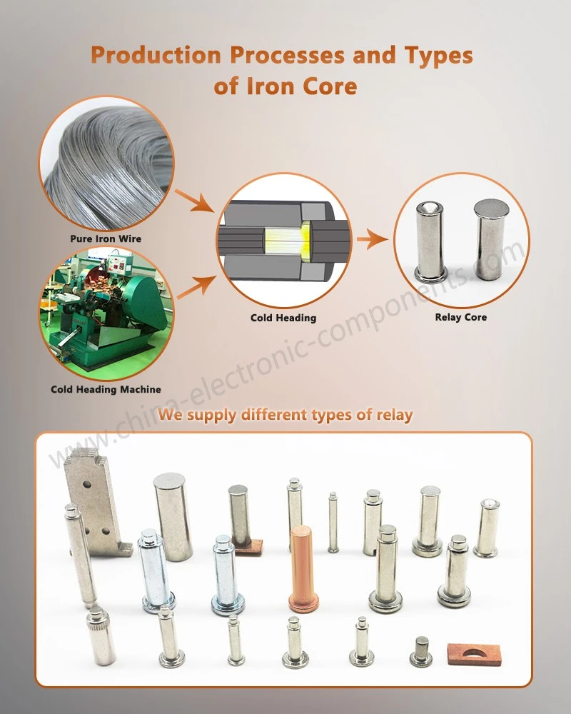
Pure iron and low-carbon magnetic iron are commonly considered for DC electromagnetic components, subject to the required magnetic properties, corrosion protection, mechanical strength, and operating environment.
Material selection should be based on certified grade data and magnetic testing rather than the generic label "pure iron."
| Material Characteristic | Engineering Significance | Verification |
| Initial permeability | Influences low-field magnetic response | Material-specific magnetic test |
| Saturation flux density | Limits usable magnetic flux | Magnetic characterization |
| Coercivity | Influences magnetization reversal | Hysteresis measurement |
| Hardness | Affects stamping force and edge quality | Hardness testing |
| Thickness variation | Affects tooling clearance and component geometry | Incoming dimensional inspection |
| Surface condition | Influences corrosion and downstream finishing | Visual and surface inspection |
Blanking Thick Magnetic Iron Without Excessive Edge Fracture
Thick-section magnetic components can develop excessive fracture zones, rollover, burrs, and dimensional distortion if the tooling and cutting conditions are not matched to the material.
Apollo's precision blanking process should be specified around the actual component thickness, magnetic iron grade, part geometry, and required edge quality.
The principal process variables are:
Punch and die clearance.
Punch edge radius and wear condition.
Press tonnage and stiffness.
Material thickness and hardness variation.
Stripper pressure and part-ejection behavior.
Burr height and cut-edge acceptance limits.
A controlled shear zone and fracture zone are normal features of conventional blanking. The objective is not to claim a completely fracture-free cut, but to limit tearing, burr formation, and edge damage to the drawing requirements.
Dimensional Inspection and Tool Wear Monitoring
For relay core and yoke production, repeatability must be maintained across the full tool life.
A suitable quality plan includes:
First-article dimensional approval.
Optical measurement of pole-face and chamfer geometry.
Flatness and parallelism inspection.
Burr-height monitoring.
SPC tracking of critical dimensions.
Tool maintenance based on measured wear and process trends.
Where required by the customer, inspection results can be incorporated into PPAP documentation and production traceability records. IATF 16949 requirements apply where the supplier and production scope fall within the relevant certified quality management system.
Request Free DFM Evaluation & Quote
Manufacturing Validation for Low-Power DC Contactor Components
From Stamped Geometry to Measured Magnetic Performance
A pole shoe or yoke cannot be qualified solely by dimensional inspection. The finished component must work within the assembled magnetic circuit.
Apollo's component validation plan can be structured around four stages:
1. Material verification: Confirm grade, thickness, hardness, and relevant magnetic properties.
2. Dimensional verification: Inspect pole-face geometry, critical profiles, flatness, and burr height.
3. Assembly validation: Check armature travel, contact seating, and mechanical interference.
4. Electrical and magnetic validation: Measure pickup behavior, holding power, release behavior, and operating repeatability.
This sequence separates stamping defects from assembly and coil-design issues during failure analysis.
Recommended Critical-to-Quality Characteristics
| CTQ Characteristic | Acceptance Basis | Failure Risk |
| Pole-face profile | Approved drawing | Nonuniform flux distribution |
| Residual contact gap | Magnetic design specification | Increased holding power |
| Face flatness | Drawing-defined tolerance | Incomplete seating |
| Burr height | Approved edge-quality limit | Mechanical interference |
| Core material properties | Material specification | Inadequate magnetic performance |
| Holding power | Below 0.5 W, if specified | Excessive energy consumption |
| Pickup and release performance | Customer test specification | Switching failure |
Numerical tolerances should be assigned after design review and capability validation. A blanket ±0.01 mm requirement is appropriate only where the drawing, function, and demonstrated manufacturing capability support it.
Reliability Validation for Smart Meters and Industrial Controllers
Low-power DC contactors used in smart meters and industrial controllers may experience wide temperature ranges, frequent switching, supply variation, and extended energized periods.
The qualification program should evaluate the assembled device under defined operating conditions, including:
Minimum and maximum rated coil voltage.
Cold and hot coil resistance.
Required pickup and release thresholds.
Long-duration holding-power stability.
Mechanical endurance and contact wear.
Environmental exposure where specified by the application.
The acceptance criteria must be defined by the customer's product specification and applicable safety requirements. Component-level dimensional compliance does not independently establish system-level reliability.
OEM Engineering Review: Design Inputs for Relay Pole Shoes and Magnetic Yokes
Before tooling release, the customer and manufacturer should agree on the magnetic, mechanical, and manufacturing requirements.
| Design Input | Required Information |
| Application | Smart meter, industrial controller, or DC contactor |
| Coil specification | Rated voltage, resistance, and drive method |
| Power target | Holding power and measurement conditions |
| Magnetic material | Grade, thickness, and required magnetic properties |
| Pole-face geometry | Chamfer, radius, profile, and reference datums |
| Contact interface | Flatness, roughness, and contact-coverage requirement |
| Production volume | Annual demand and expected tool life |
| Quality documentation | Inspection plan, traceability, and PPAP requirements |
Apollo Electronic Components (Xiamen) Co., Ltd. supports precision metal stamping and magnetic component manufacturing for relay cores, pole shoes, yokes, and related steel stamping parts. Final process parameters and acceptance limits should be established through drawing review, material qualification, tooling trials, and component-level performance validation.
Frequently Asked Questions
1. How can a relay pole shoe manufacturer support a DC contactor with holding power below 0.5 W?
The manufacturer controls pole-face geometry, material properties, burr height, and contact flatness. The assembled contactor must then pass holding-power, pickup, release, and endurance tests under the customer's specified voltage and temperature conditions.
2. What contact flatness is required for magnetic yoke air gap optimization?
The required flatness depends on pole-face dimensions, magnetic force, and the allowable residual air gap. An 85% contact-coverage target can be used when specified by the design, but it should be verified alongside flatness and magnetic performance.
3. What quality documents can be requested for precision steel-stamped relay cores?
Typical deliverables include dimensional inspection reports, material certificates, control plans, process capability data, and PPAP documentation where required. The exact package depends on customer-specific requirements and the supplier's applicable quality certifications.
contact us

Send Inquiry