



Vacuum Furnace Brazing of AgW and CuW Refractory Contacts in Heavy-Duty Air Circuit Breakers (ACB)
Oct 27, 2026
Leave a message
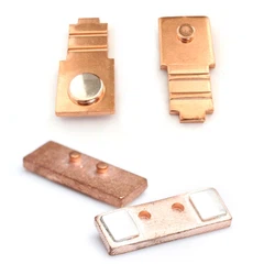
Silver-tungsten (AgW) and copper-tungsten (CuW) contacts are used in demanding switching applications where arc erosion resistance, thermal stability, and electrical conduction must be balanced within a defined contact geometry. Vacuum furnace brazing joins these refractory contact materials to conductive support components while limiting oxidation and flux contamination. Joint integrity depends on substrate preparation, filler-metal compatibility, furnace temperature uniformity, vacuum quality, and verified bonded area-not vacuum processing alone.

AgW and CuW Arc Contacts: Thermal Shock and Electrical Loads During ACB Fault Interruption
Why tungsten-based contact materials are used in high-current switching
Heavy-duty air circuit breakers (ACBs) must interrupt fault currents that can reach tens of kiloamperes, depending on the device's rated service and ultimate short-circuit breaking capacities. During interruption, an electrical arc creates intense localized heating, material transfer, and repeated thermal cycling at the contact surface.
Tungsten has a melting point of approximately 3,422°C and retains high-temperature strength relative to many common conductive metals. In AgW and CuW composite contacts, the tungsten-rich phase contributes resistance to arc erosion, while the conductive phase supports current transfer and heat dissipation. The actual performance depends on composition, density, microstructure, contact geometry, and the breaker's opening speed and arc-control design.
| Contact material | Typical material characteristics | Main design consideration |
| AgW (silver-tungsten) | Silver-rich conductive phase combined with tungsten for arc resistance | Balance conductivity, contact resistance, and erosion resistance for the switching duty |
| CuW (copper-tungsten) | Copper conductive phase combined with tungsten for arc resistance and thermal stability. | Control conductivity, thermal transport and erosion performance according to the selected composition |
| Pure copper support | High electrical conductivity and useful heat-transfer capability | Requires a suitable contact interface and protection against excessive arc damage |
| Silver-based contact support or backing | Can provide a conductive joining interface in selected assemblies | Filler compatibility and service temperature must be evaluated for the complete joint |
AgW and CuW are typically composite materials rather than homogeneous tungsten alloys. Their properties vary with the tungsten fraction, manufacturing route, and resulting microstructure. Material designation alone is insufficient to establish a contact's interruption performance.
Joint integrity under arc-induced thermal cycling
The brazed interface connects the refractory contact element to its support or backing. During switching, temperature gradients can produce differential expansion between the contact composite, filler metal, and support component. Repeated cycles may initiate cracking, reduce effective bonded area, or increase electrical resistance.
The principal design risks include:
Differential thermal expansion: AgW, CuW, copper, and brazing filler metals have different thermal-expansion coefficients. Joint geometry and filler-layer thickness must accommodate the resulting strain.
Localized current constriction: Incomplete bonding or void clusters reduce the effective conductive area and can create localized heating.
Thermal fatigue: Repeated heating and cooling can propagate defects at the interface, particularly near corners or abrupt changes in section.
Contact-face distortion: Excessive or uneven brazing heat can alter flatness or introduce distortion that affects the final contact gap and pressure distribution.
Interfacial contamination: Oxides, machining residues, and trapped contaminants can inhibit wetting and weaken the joint.
The brazed joint must therefore be qualified as part of the finished contact assembly. A visually acceptable external fillet does not prove that the buried interface has adequate bonded area.
Vacuum Furnace Brazing AgW Contacts: Wetting, Filler Selection and Thermal Control
Why vacuum brazing is suitable for refractory contact assemblies
Tungsten-rich materials are difficult to join using conventional brazing approaches because wetting depends strongly on surface condition, filler chemistry, and process temperature. Vacuum furnace brazing reduces exposure to atmospheric oxygen and can limit oxide formation on appropriately prepared surfaces. It also avoids introducing conventional flux residues into the joint when the process is designed to operate without flux.
However, vacuum does not guarantee 100% wetting. Wetting remains dependent on the filler-metal system, the surface chemistry, the contact material's composition and porosity, the joint clearance, and the thermal cycle. Certain material combinations may require a compatible metallization layer or another qualified surface treatment before brazing.
A process specification should define:
1. Substrate composition and condition, including the AgW or CuW grade and the support material.
2. Surface preparation and the maximum permitted interval between cleaning and furnace loading.
3. Filler-metal composition, form, placement, and compatibility with the service temperature.
4. Joint clearance and fixture design to maintain alignment during heating.
5. Furnace vacuum level, heating rate, soak temperature, dwell time and cooling conditions.
6. Post-braze inspection, including bonded-area assessment and dimensional verification.
Brazing filler-metal selection for AgW and CuW assemblies
Filler metal selection must account for wetting, service temperature, electrical resistance, joint ductility, and the thermal limits of all components. A filler that wets one substrate effectively may not provide acceptable bonding to another without a compatible surface condition.
| Selection criterion | Engineering requirement | Failure risk if uncontrolled |
| Wetting compatibility | Demonstrated wetting on the specified AgW/CuW grade and support material | Incomplete joint coverage or unbonded regions |
| Brazing temperature | Above the filler's liquidus and within the qualified thermal limits of the assembly | Incomplete flow, excessive reaction, or component distortion |
| Electrical properties | Acceptable resistance for the intended current path | Additional voltage drop and local heating |
| Thermal expansion | Joint can tolerate differential expansion during service | Interfacial cracking under thermal cycling |
| Service temperature | Filler retains adequate mechanical and electrical integrity at the expected operating temperature. | Joint softening, creep or premature degradation |
| Chemical compatibility | Limited detrimental reaction with the refractory composite and support | Brittle reaction layers or weakened interfaces |
Filler-metal chemistry and brazing temperature must be chosen for the actual material combination. It is not technically sound to prescribe one universal filler alloy or furnace temperature for all AgW and CuW contacts.
Furnace atmosphere, degassing and temperature uniformity
Vacuum brazing is a controlled thermal process, not simply heating a part inside a vacuum chamber. Oils, polishing compounds, cleaning residues,s and moisture can outgas during the cycle. Residual contamination may affect wetting or contribute to porosity if gas becomes trapped at the interface.
The production process should control both the load preparation and the furnace cycle.
| Process variable | Purpose | Recommended control |
| Cleaning and drying | Reduce hydrocarbons, moisture, and particles | Use a validated cleaning procedure and defined handling conditions |
| Vacuum level | Limit oxidation and support the qualified brazing atmosphere | Record pressure against the approved cycle; define alarms and rejection limits |
| Heating rate | Manage thermal gradients and outgassing | Establish a qualified ramp profile for the actual furnace load |
| Soak temperature | Achieve the required filler-metal flow and wetting | Use calibrated temperature measurement and a validated operating window |
| Temperature uniformity | Limit variation between parts and load positions | Qualify the furnace working zone and representative load configuration |
| Dwell time | Allow sufficient filler flow without excessive reaction | Establish through representative brazing trials |
| Cooling rate | Control thermal gradients and residual stress | Specify cooling conditions based on the joint materials and geometry |
The furnace cycle should be validated using representative production loads. Furnace temperature uniformity and actual part temperature are not necessarily identical, particularly when part mass, fixture design, and load density vary.
Request Free DFM Evaluation & Quote

Brazed Joint Inspection: Ultrasonic Testing, Void Ratio and Bonded-Area Verification
Defining the acceptance criteria for brazed AgW/CuW contacts
A nominal void ratio of 5% or less can be used as a project-specific acceptance target for a brazed interface, but it is not a universal acceptance limit for all ACB contacts. The permissible defect size, defect location, and required bonded area must be defined by the contact design, electrical duty, mechanical loading, and customer specification.
Total void area alone may not predict joint reliability. A single large void near a highly loaded edge can be more damaging than several small, distributed pores with the same cumulative area. Acceptance criteria should therefore consider both the total indication area and the location, size, and distribution of individual indications.
A robust inspection plan distinguishes between:
Void ratio: The estimated projected area of detected voids divided by the evaluated joint area.
Bonded-area ratio: The estimated area of effective bonding divided by the nominal interface area.
Maximum individual indication: The largest detected unbonded region or pore.
Edge-defect location: Whether an indication intersects a joint edge or a critical stress-transfer region.
Electrical performance: Whether the assembled contact meets the specified resistance and temperature-rise limits.
Where the drawing specifies a void ratio of no more than 5%, the inspection procedure must also define how the evaluated area is measured and how edge indications are treated.
Ultrasonic testing versus destructive metallographic inspection
Ultrasonic testing (UT) can help identify interface discontinuities, but its suitability depends on contact dimensions, joint geometry, material attenuation, surface access, and the acoustic properties of the AgW/CuW composite. Small, curved, or irregular interfaces may be difficult to evaluate reliably without a validated inspection procedure.
For dense refractory contact assemblies, the inspection method should be selected through trials using representative joints and known or independently characterized defects. Destructive metallography can provide direct evidence of the interface condition on sampled parts, while ultrasonic inspection may support non-destructive screening when adequate detection capability has been demonstrated.
| Inspection method | Primary information | Advantages | Limitations |
| Ultrasonic testing (UT) | Internal discontinuities and interface indications | Non-destructive; can support production inspection when geometry and material permit | Detection sensitivity depends on geometry, calibration, and material response |
| Metallographic cross-section | Direct view of the brazed interface, filler distribution and voids | High-resolution assessment of local joint structure | Destructive; only evaluates the sampled section or location |
| X-ray radiography or computed tomography | Internal density variations and three-dimensional defect distribution, depending on technique | Can reveal internal features inaccessible to surface inspection | Resolution, contrast and detectability depend on material thickness and defect geometry |
| Four-wire resistance measurement | Electrical resistance of the specified current path | Direct electrical performance measurement | Does not independently reveal defect location or prove mechanical integrity |
| Mechanical testing | Joint strength under a defined loading mode | Evaluates load-bearing performance | May not reproduce service loading; usually destructive or sample-based |
For production release, the selected method should be supported by a documented procedure, calibrated equipment, representative reference samples, and defined acceptance criteria. A non-destructive inspection result should not be reported as a quantitative void ratio unless the method has been demonstrated to provide that measurement with adequate accuracy.
Correlating void ratio with electrical and mechanical performance
The relationship between void ratio and performance depends on the joint's shape and the spatial distribution of defects. Voids can reduce the effective conductive area, increase current density around the remaining bonded regions, and create local thermal gradients. At the same time, defects near an interface edge may increase local stress concentration under thermal cycling.
A project validation plan should correlate the chosen non-destructive inspection method with representative metallographic sections and electrical measurements.
| Verification stage | Measurement | Engineering purpose |
| Initial inspection | Interface indications and dimensional condition | Establish the baseline quality of the brazed assembly |
| Bonded-area evaluation | Void ratio, defect distribution, and edge location where measurable | Verify compliance with the defined joint acceptance criteria |
| Electrical testing | Four-wire resistance at specified measurement points | Detect excessive resistance or unstable electrical performance |
| Thermal evaluation | Temperature rise under a defined current profile | Identify local heating associated with resistance or current constriction |
| Mechanical or fatigue validation | Performance under specified loads and cycles | Evaluate joint durability under representative service conditions |
| Post-test inspection | Repeat electrical and structural checks | Identify defect growth or changes after loading |
Acceptance limits should be established before production validation. If a 5% maximum void ratio is specified, the associated test method, measurement uncertainty, and sampling plan should be agreed with the customer. A passing void-ratio result does not replace electrical, thermal, or mechanical qualification.

Large-Format ACB Arc Contact Manufacturing: Geometry, Assembly and Final Inspection
Managing irregular contact profiles and large bonded interfaces
Heavy-duty ACB arc contacts may use non-circular profiles, stepped sections, curved surfaces or large contact faces. These geometries increase the importance of fixture repeatability, filler placement, and dimensional control during vacuum brazing.
A larger nominal interface does not automatically produce a larger effective bonded area. Filler distribution can vary with joint clearance, surface flatness, fixture pressure, and the component's position within the furnace load. Irregular shapes may also develop uneven thermal gradients during heating and cooling.
The engineering review should identify critical-to-quality features before tooling and fixtures are released:
Contact-face dimensions and flatness: Control the geometry that determines the mating interface and contact pressure.
Brazed interface dimensions: Define the nominal joint area and the regions where unbonded indications are unacceptable.
Filler placement: Prevent displacement, incomplete coverage, or excessive filler accumulation during heating.
Fixture rigidity and alignment: Maintain the designed position without imposing unnecessary stress on brittle or porous contact materials.
Post-braze machining allowance: Account for distortion and the finishing operations required to achieve the final contact profile.
Traceability: Link the finished assembly to the specified materials, furnace cycle, and inspection records.
The drawing should distinguish nominal dimensions from functional tolerances. Tight tolerances should be applied to features that affect contact alignment, electrical performance, or assembly fit rather than indiscriminately to every surface.
Post-braze machining and dimensional verification
Some assemblies require grinding or machining after brazing to achieve the final contact profile, surface condition, or mounting dimensions. These operations must avoid introducing cracks, edge chipping, or excessive residual stress into the refractory contact material or brazed interface.
Dimensional verification should use a datum structure that reflects the finished assembly's mounting and mating requirements. Coordinate measuring machine (CMM) inspection can verify complex profiles and positional relationships where the part geometry and measurement strategy are suitable.
| Quality characteristic | Verification approach | Acceptance basis |
| Contact-face profile | CMM, optical measurement, or a suitable dedicated gauge | Approved drawing |
| Flatness and parallelism | CMM or validated surface measurement method | Functional requirements for the contact interface |
| Mounting-hole position | CMM or dedicated inspection fixture | Datum-based positional tolerance |
| Brazed joint integrity | Qualified UT, radiography, metallography, or a defined combination | Approved joint acceptance criteria |
| Electrical resistance | Four-wire Kelvin measurement | Specified resistance and tolerance |
| Surface defects | Visual inspection under defined lighting and magnification where required | Approved visual criteria |
| Lot consistency | Statistical dimensional monitoring and traceability | Customer control plan and agreed process-capability criteria |
CMM results establish dimensional conformity; they do not prove internal brazing integrity. Likewise, a sound brazed interface does not guarantee that the final contact profile meets its assembly tolerances. These characteristics require separate verification.
Production qualification and automotive-style quality documentation
Where the customer requires an automotive-style quality package, the control plan should connect material certification, furnace-cycle records, dimensional inspection, joint-integrity testing, and electrical verification to the approved part revision.
IATF 16949 certification should only be claimed for the specific manufacturing site when its certification status has been verified. PPAP Level 3 documentation may be required by the customer, but the submission level and approval criteria must be agreed for each program.
A suitable qualification package can include:
Material certificates for the specified AgW/CuW grade, support material and brazing filler.
Surface-preparation and furnace-cycle records, including defined process parameters.
Dimensional inspection reports for contact faces, mounting features and overall assembly geometry.
Validation data for the selected non-destructive inspection method.
Metallographic results from representative qualification samples.
Electrical resistance and, where specified, temperature-rise test reports.
Control plans, measurement-system evidence, and lot traceability.
Approved deviation and change-control procedures for materials, tooling, filler chemistry, or brazing parameters.
Request Free DFM Evaluation & Quote
Engineering Review Checklist for Vacuum-Brazed AgW and CuW Contacts
Data required for an OEM quotation and DFM review
A technically valid quotation requires the material, geometry, service conditions, and quality requirements that determine process feasibility. For a circuit breaker arc contact assembly, the initial review should establish:
| Input data | Why it matters |
| AgW/CuW composition, grade, and density requirements | Determines material behavior and the suitability of the joining process |
| Support material and interface configuration | Establishes filler compatibility and thermal-expansion considerations |
| 2D drawing and 3D CAD model | Defines the contact profile, nominal joint area, and critical dimensions |
| Brazing filler specification, if fixed | Constrains the qualified thermal cycle and joint chemistry |
| Rated current and short-circuit interruption requirements | Provides context for electrical and thermal qualification |
| Operating and thermal-cycle conditions | Defines the required durability assessment |
| Maximum void ratio and bonded-area criteria | Establishes the inspection acceptance basis |
| Annual demand and batch size | Informs furnace loading, fixture design, and inspection planning |
| Required quality documentation | Defines the validation records and customer submission package |
Short-circuit performance is a property of the complete circuit breaker design and its validated interruption system. A brazed contact assembly cannot independently establish an ACB's rated breaking capacity. Contact material, geometry, operating mechanism, arc chamber, and test conditions must be considered together.
Apollo supply scope for AgW/CuW brazed contact assemblies
Apollo Electronic Components (Xiamen) Co., Ltd can review drawings and technical requirements for refractory contact assemblies intended for industrial switching equipment. The manufacturing route should be confirmed against the actual component design and the capabilities of the supplying production site.
The engineering discussion should focus on material compatibility, joint configuration, furnace-cycle requirements, dimensional tolerances, and the inspection method needed to verify the buried interface. For large or irregular AgW/CuW contacts, these decisions should be resolved before production tooling and qualification samples are committed.
The objective is a documented manufacturing specification that connects the drawing to repeatable process conditions and measurable acceptance criteria. Where the customer specifies a void ratio of no more than 5%, the inspection method and its demonstrated detection capability should be included in the agreed quality plan.
FAQ: Vacuum Brazing AgW Contacts and CuW ACB Assemblies
What void ratio is acceptable for vacuum-brazed AgW and CuW contacts?
A project may specify a maximum void ratio of 5%, but this is not a universal industry limit. Acceptance must define the inspection method, evaluated joint area, maximum individual indication, and treatment of edge defects.
Can vacuum brazing guarantee 100% wetting on tungsten-based contacts?
No. Vacuum reduces oxidation risk but does not guarantee complete wetting. Results depend on filler chemistry, substrate condition, surface preparation, joint clearance, and the qualified furnace cycle. Representative trials and joint-integrity verification are required.
What inspection documents should an OEM supplier provide for ACB brazed contacts?
The agreed package may include material certificates, furnace-cycle records, dimensional reports, qualified non-destructive inspection results, metallographic samples, electrical measurements, and lot traceability. PPAP documentation should follow the customer's specified submission level.
contact us

Send Inquiry