










Optimizing Magnetic Performance: Pure Iron Cores and Annealing for Latching Relays
Sep 12, 2026
Leave a message
Low-Power Latching Relays: Why Core Material and Coercivity Matter
A latching relay must maintain its magnetic state without continuous coil energization. The magnetic circuit therefore depends on a low-loss pure iron relay core, controlled residual magnetism, low coercive force, and stable dimensional accuracy rather than continuous holding current. For smart meters, energy-management equipment, and battery-powered control systems, the target is typically a core geometry and heat-treatment process that provides reliable magnetic attraction and release with a short excitation pulse.
For procurement and engineering teams, the material specification should not stop at "pure iron." The practical performance of a latching relay iron core is determined by iron grade, carbon and impurity content, cold-working history, annealing atmosphere, surface treatment, dimensional tolerance, and the final magnetic circuit design.
A production specification should therefore connect five parameters:
DT4C / DT4E electric pure iron with controlled chemical composition and magnetic properties.
Cold heading, stamping, turning, or machining deformation controlled before final annealing.
Vacuum or controlled-atmosphere annealing to reduce residual stress and coercive force.
CMM inspection for pole geometry, concentricity, length, and dimensional tolerance.
Zinc or nickel plating selected according to corrosion requirements without unnecessarily increasing the non-magnetic surface layer.
For a high-volume relay program, these variables should be validated through material certificates, magnetic testing, dimensional inspection, plating-thickness measurement, and PPAP documentation under an IATF 16949 quality system.

DT4C and DT4E Electrical Pure Iron: Material Selection for Magnetic Relay Cores
Electric pure iron is used where the magnetic circuit requires high permeability and low magnetic reluctance while avoiding the higher electrical resistivity or alloying characteristics associated with some other magnetic materials.
DT4C and DT4E are commonly considered for electromagnetic components such as relay cores, yokes, pole pieces, armatures, and magnetic pole structures. However, grade selection should be based on the actual magnetic circuit and heat-treatment condition rather than material name alone.
DT4C / DT4E Magnetic Performance Must Be Verified After Processing
The same nominal material can show different magnetic behavior after stamping, cold forming, machining, or grinding. Plastic deformation introduces lattice defects and residual stress, increasing magnetic hysteresis and potentially changing coercive force.
For a latching relay, this can affect:
Pull-in voltage
Drop-out voltage
Pulse duration
Magnetic holding force
Residual magnetism
Coil energy consumption
Switching repeatability
Temperature-dependent magnetic behavior
A useful engineering comparison is:
| Parameter | Cold-worked pure iron | Annealed pure iron |
| Residual stress | Higher | Reduced |
| Magnetic domain mobility | Restricted | Improved |
| Coercive force | Generally higher | Generally lower |
| Hysteresis loss | Higher | Lower |
| Magnetic permeability | Reduced by deformation | Improved |
| Dimensional stability | Depends on process | Improved when stress is relieved |
| Suitability for precision latching relay core | Requires validation | Generally preferred |
The final magnetic properties should be measured on production-representative samples rather than inferred solely from the raw-material certificate.
C1100 Copper and C2680 Brass Are Not Substitutes for a Magnetic Core
Material substitution must also consider magnetic permeability, conductivity, mechanical strength, and forming behavior.
| Material | Typical role | Magnetic behavior | Electrical conductivity | Typical relay relevance |
| DT4C / DT4E | Magnetic core/pole | Ferromagnetic | Moderate | Core magnetic circuit |
| C1100 pure copper | Conductive component | Essentially non-magnetic | Very high, commonly around 100% IACS | Busbars, terminals, conductive parts |
| C2680 brass | Structural/contact component | Weakly magnetic to effectively non-magnetic in normal relay use | Lower than copper | Terminals, stamped hardware |
C1100 pure copper is selected primarily for electrical conductivity. C2680 brass is often selected for its combination of formability, strength, and corrosion resistance. Neither should be specified as a direct replacement for an electrical pure iron relay core where magnetic force is part of the functional requirement.
Stamping Geometry Directly Affects the Magnetic Circuit
For stamped relay cores, dimensional control is not only a mechanical requirement. Pole-face geometry determines the effective air gap and magnetic flux path.
A burr, angular distortion, or excessive flatness deviation at the pole face can change the effective contact area between magnetic components. A dimensional specification such as ±0.01 mm may be appropriate for selected critical features, but the actual tolerance must be established from magnetic-circuit sensitivity and assembly requirements.
For precision parts, the inspection plan can include:
Optical dimensional inspection
CMM inspection
Gauge inspection
Flatness measurement
Concentricity measurement
Surface roughness measurement
Burr-height inspection
Magnetic performance testing
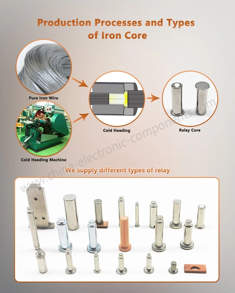
In-Die Riveting and Assembly Accuracy
Where the core is integrated with additional stamped magnetic or mechanical components, in-die riveting can reduce secondary assembly operations and improve positional repeatability.
However, riveting force must be controlled because excessive deformation can introduce local residual stress into the magnetic component. The process window should include:
Rivet diameter
Material thickness
Punch geometry
Forming displacement
Riveting force
Rivet-head height
Final assembly clearance
For automotive or metering applications, the validated process should connect these variables to dimensional capability and functional magnetic testing.
Request Free DFM Evaluation & Quote
Vacuum Annealing: Reducing Residual Stress and Coercive Force
Annealing is one of the most important process variables for a precision pure iron relay core.
Stamping, cold heading, bending, turning, grinding, and other mechanical processes modify the metal's internal stress state. These changes can restrict magnetic-domain movement and increase hysteresis. For a latching relay, this can translate into inconsistent magnetic response even when the raw material itself meets specification.
Vacuum Annealing Under Controlled Thermal Profiles
A typical process consists of controlled heating, temperature soaking, controlled cooling, and vacuum or inert-atmosphere protection.
The exact thermal cycle must be established according to:
DT4C or DT4E grade
Part geometry
Maximum section thickness
Previous deformation level
Furnace loading
Required magnetic performance
Surface oxidation limits
Subsequent plating process
A generic process window should not be copied between different core geometries. Thick and thin sections have different thermal response characteristics, and excessive temperature or uncontrolled cooling can affect dimensional stability.
Why Annealing Changes Relay-Core Magnetic Behavior
Magnetic performance is strongly related to domain-wall movement.
Mechanical deformation introduces dislocations and residual stress. These act as pinning sites for magnetic domains. Stress-relief annealing reduces these barriers and allows the magnetic domains to respond more readily to an applied field.
The engineering objective is not simply "softening the metal." It is to establish a repeatable magnetic state with:
Lower coercive force
Higher effective permeability
Lower hysteresis loss
Stable pull-in behavior
Stable release behavior
Reduced magnetic variation between production lots
Magnetic Testing Should Follow the Actual Manufacturing Route
A robust validation sequence compares:
Raw material → stamped part → annealed part → plated part → assembled relay
Testing only the incoming raw material can miss process-induced magnetic degradation.
A production control plan may include:
| Manufacturing stage | Recommended control | Engineering purpose |
| Incoming material | Chemical composition + material certificate | Confirm DT4C/DT4E grade |
| Stamping | Dimensional inspection + burr control | Protect magnetic geometry |
| Pre-annealing | Deformation/process record | Establish thermal-cycle input |
| Annealing | Furnace temperature + vacuum/atmosphere record | Control stress relief |
| Post-annealing | Magnetic-property testing | Verify magnetic response |
| Plating | Coating thickness test | Control corrosion layer |
| Final assembly | Pull-in/release verification | Confirm relay function |
| Lot release | Traceability + inspection records | Support PPAP and customer audit |
For Tier 1 programs, furnace records should be traceable to production lots. If magnetic performance is a special characteristic, the control plan and PFMEA should explicitly identify the annealing process as a potential source of variation.
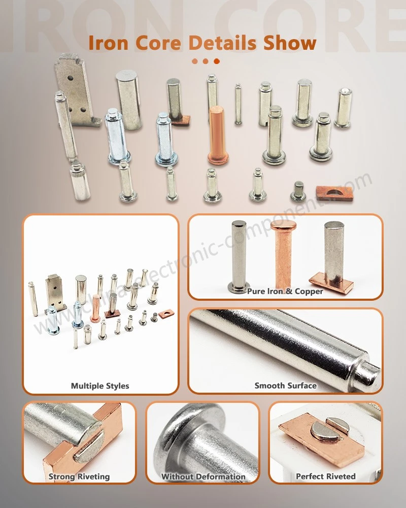
Vacuum Annealing vs Conventional Atmosphere Annealing
| Factor | Vacuum annealing | Conventional atmosphere annealing |
| Surface oxidation | Low when properly controlled | Higher risk |
| Surface cleanliness | High | Depends on atmosphere |
| Magnetic-property consistency | High with controlled recipe | Process-dependent |
| Post-annealing cleaning | Often reduced | May require additional treatment |
| Furnace traceability | Highly controllable | Depends on equipment |
| Suitable for precision relay cores | Yes | Yes, when atmosphere is validated |
The correct selection depends on the required surface condition, magnetic specification, furnace capability, production volume, and downstream plating process.
Zinc vs Nickel Plating: Corrosion Protection Without Excessive Magnetic Penalty
A relay core may require surface protection because pure iron is susceptible to oxidation. The challenge is that plating adds another material layer to a component whose primary function is magnetic.
The plating specification should therefore balance:
Corrosion resistance + dimensional control + adhesion + surface condition + magnetic performance.
Zinc Plating for Cost and Corrosion Control
Zinc plating provides sacrificial corrosion protection and is widely used for steel and iron components.
For relay cores, engineering controls should include:
Zinc coating thickness
Passivation type
Hydrogen-management requirements
Surface cleanliness
Adhesion
Salt-spray validation where specified
Dimensional buildup on critical features
A coating thickness of several micrometers can be acceptable for many applications, but the final specification should come from the required corrosion class and dimensional stack-up.
Nickel Plating for Surface Durability and Environmental Resistance
Nickel plating provides a harder, more wear-resistant surface and can offer better resistance to certain environmental conditions.
However, nickel is not electrically or magnetically equivalent to the underlying pure iron. A plating layer can also change critical dimensions, especially on precision pole faces, press-fit regions, or interfaces with an armature.
For this reason, the plating process should be validated together with the magnetic assembly.
Zinc vs Nickel: Engineering Selection Matrix
| Parameter | Zinc plating | Nickel plating |
| Primary function | Sacrificial corrosion protection | Surface protection and durability |
| Typical appearance | Silver/gray after passivation | Metallic bright/semi-bright |
| Dimensional buildup | Must be controlled | Must be controlled |
| Wear resistance | Moderate | Higher |
| Corrosion strategy | Sacrificial protection | Barrier protection |
| Relay-core magnetic validation | Required | Required |
| Cost | Generally lower | Generally higher |
| Best use case | Cost-sensitive protected relay components | Higher surface durability requirements |
The key point is that plating thickness should never be specified independently of the magnetic circuit.
If the pole face has a tight air-gap requirement, even a small coating buildup can affect the final assembly condition. Critical surfaces may therefore require selective plating, masking, post-plating dimensional control, or a design allowance.
Coating Thickness Measurement and Final Magnetic Verification
A production inspection plan can combine:
X-ray fluorescence coating-thickness testing
Micrometer or CMM dimensional measurement
Visual inspection
Adhesion testing
Corrosion testing according to customer specification
Pull-in and release testing
Coil-current verification
Magnetic holding-force verification
For plating thickness, the acceptance range should be defined as a controlled process specification rather than simply stating "nickel plated" or "zinc plated."
Manufacturing Control for ±0.01 mm Relay-Core Features Under IATF 16949
A production-ready electromagnetic iron core manufacturer must control the complete process chain rather than inspect only finished dimensions.
For automotive, smart-meter, and energy-control applications, the recommended quality structure connects material, tooling, forming, annealing, plating, inspection, and final functional testing.
Progressive Die Stamping With Controlled Burr and ±0.01 mm Features
Progressive stamping is suitable for high-volume relay components when geometry and material thickness are compatible with the process.
Critical parameters include:
Strip thickness
Die clearance
Punch-to-die alignment
Cutting-edge condition
Feed accuracy
Strip flatness
Burr height
Tool wear
Part deformation
Tool wear changes cutting clearance over time. Therefore, die maintenance intervals should be linked to measured part capability rather than only a calendar schedule.
Tool-Life Management and Process Capability
A production tooling plan should document:
Initial tool qualification
First-piece inspection
Cpk/Ppk monitoring for critical dimensions
Tool-shot tracking
Punch and die replacement criteria
Preventive maintenance
Spare-component management
Corrective-action records
For high-volume relay production, the supplier should be able to provide traceability from finished parts back to material lot, stamping die, annealing batch, plating batch, and inspection record.
CMM Inspection for Magnetic-Circuit Geometry
CMM inspection is particularly useful where several geometric features interact.
Typical characteristics include:
| Feature | Example control method | Potential functional effect |
| Pole length | CMM | Magnetic circuit geometry |
| Pole-face flatness | CMM / optical measurement | Armature contact |
| Concentricity | CMM | Assembly alignment |
| Hole position | CMM / vision | Riveting or assembly |
| Thickness | Micrometer / CMM | Magnetic reluctance and fit |
| Burr height | Optical inspection | Assembly interference |
| Surface condition | Visual / roughness test | Contact interface |
The exact tolerance must be established from the relay design. A blanket ±0.01 mm requirement on every feature can increase manufacturing cost without improving relay performance; conversely, insufficient control on a magnetic-gap feature can cause functional variation.
Quality Documentation for PPAP Level 3
For automotive programs, a PPAP Level 3 submission may include:
Part Submission Warrant
Process flow diagram
PFMEA
Control plan
Dimensional results
Material certification
Performance test results
MSA / gauge studies
Initial process capability
Tooling information
Sample production parts
Where the relay core is classified as a special characteristic, magnetic-property data should be connected to the control plan and process capability analysis.
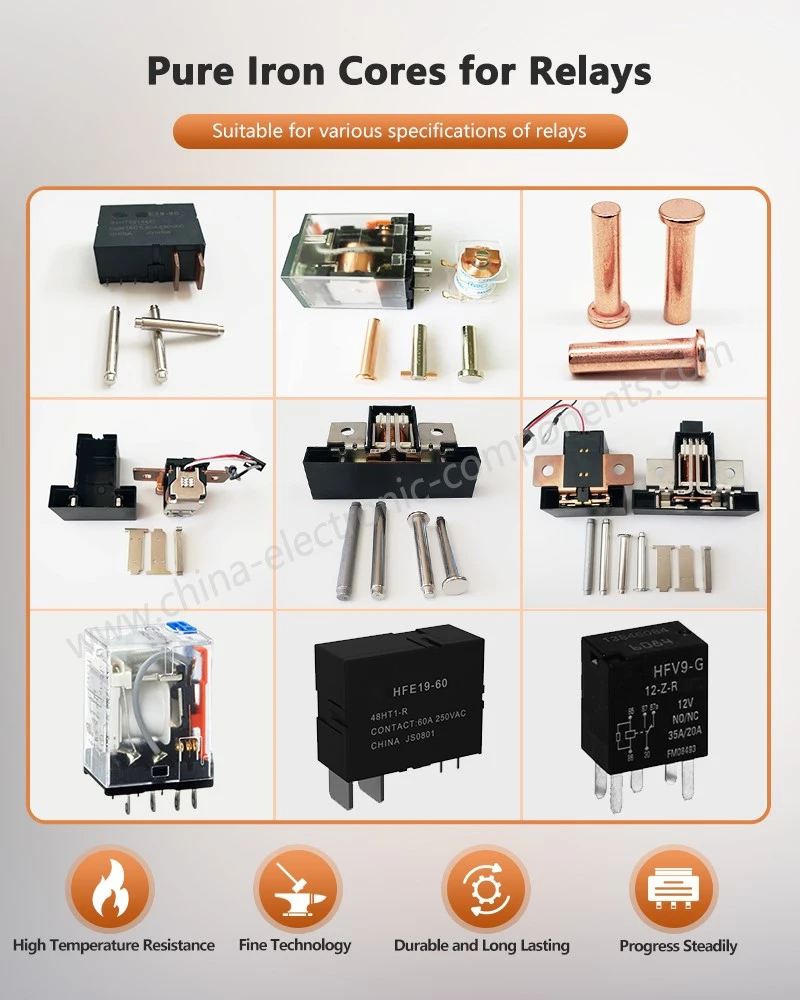
Engineering Selection Matrix: From Raw Material to Latching Relay Assembly
When sourcing a latching relay iron core, procurement teams should evaluate the entire manufacturing route rather than compare unit prices between nominally identical components.
| Evaluation item | Minimum engineering question | Recommended evidence |
| Material | Is the grade controlled as DT4C/DT4E? | Material certificate |
| Chemistry | Are composition limits traceable by lot? | Mill certificate/supplier record |
| Forming | How is deformation controlled? | Process flow + PFMEA |
| Annealing | Is the thermal recipe controlled and recorded? | Furnace records |
| Magnetic performance | Are post-annealing properties verified? | Magnetic test report |
| Dimensions | Are critical features measured statistically? | CMM / capability report |
| Plating | Is coating thickness controlled? | XRF report |
| Corrosion | Has the selected finish passed the specified test? | Laboratory report |
| Assembly | Are pull-in/release parameters verified? | Functional test record |
| Quality | Can production records support PPAP Level 3? | PPAP package |
| Traceability | Can finished parts be traced to process lots? | Lot traceability system |
The preferred supplier is therefore not simply a stamping company. The manufacturing capability should cover precision metal forming, stress-relief annealing, surface treatment, dimensional inspection, magnetic validation, and production traceability.
Recommended Specification for a Pure Iron Relay Core RFQ
A purchasing drawing or RFQ should provide enough information for the supplier to evaluate manufacturability before quotation.
Recommended information includes:
Material: DT4C / DT4E electrical pure iron
Raw-material thickness or diameter
Finished dimensions
Critical tolerance zones
Pole-face flatness
Burr-height requirement
Magnetic performance target
Annealing requirement
Plating type
Plating thickness
Corrosion-test requirement
Surface roughness
Assembly method
Pull-in/release requirements
Environmental operating temperature
Annual volume
Prototype quantity
PPAP requirement
Inspection standard
Packaging and traceability requirements
For new components, supplying a 2D drawing, 3D CAD model, annual demand, material requirement, and target functional parameters allows an electromagnetic iron core manufacturer to conduct a DFM review before tooling investment.
Engineering Conclusion: Control the Magnetic State, Not Just the Metal Geometry
The performance of a latching relay core is determined by the interaction between material composition, mechanical deformation, annealing, surface treatment, dimensional accuracy, and the final magnetic circuit.
DT4C or DT4E can provide the required ferromagnetic foundation, but stamping-induced stress can increase coercive force and reduce magnetic response. Controlled vacuum annealing can reduce this process-induced magnetic degradation. Zinc or nickel plating can provide corrosion protection, but coating thickness must be included in the dimensional and magnetic validation plan.
For high-volume smart-meter, EV control, ESS, and power-electronics applications, the practical sourcing requirement is therefore:
Controlled pure iron material → precision forming → stress-relief annealing → controlled plating → CMM inspection → magnetic functional testing → PPAP Level 3 traceability.
Apollo Electronic Components (Xiamen) Co., Ltd. supports precision electromagnetic components through metal stamping, forming, machining, surface treatment, dimensional inspection, and production-quality control. For a new latching relay iron core, engineering teams can provide the drawing or CAD data for DFM review, material/process assessment, prototype planning, and volume-production evaluation.
FAQ: Pure Iron Relay Core Procurement and Process Control
What is the typical PPAP Level 3 delivery cycle for a latching relay iron core?
The cycle depends on tooling complexity, sample quantity, testing requirements, and customer documentation. A production program should define tooling, T1 samples, dimensional validation, magnetic testing, and PPAP submission milestones before purchase-order release.
How can manufacturers control stamping die life for high-volume pure iron relay cores?
Die life should be managed through shot-count records, preventive maintenance, critical-dimension capability, burr monitoring, and punch/die wear inspection. Replacement criteria should be based on measured process drift rather than shot count alone.
How is relay-core plating thickness verified without compromising magnetic performance?
X-ray fluorescence (XRF) can measure zinc or nickel coating thickness non-destructively. Critical dimensions and final pull-in/release performance should then be verified after plating to confirm that coating buildup has not changed the magnetic air gap.
contact us

Send Inquiry