










Analysis of the Plastic-Dipping Insulation Process for Copper Busbars: Materials, Manufacturing Workflow, and Application Characteristics in Energy Storage Systems
Sep 17, 2026
Leave a message
As energy storage systems, power electronics, and new energy electrical systems evolve toward higher voltages, higher currents, and greater integration, copper busbars are required to do more than just transmit electrical energy; their insulation structure, environmental durability, and assembly reliability have become critical considerations in electrical connection design. Dip coating is a well-established insulation method for busbars; it involves forming a continuous polymer insulation layer on the busbar surface to electrically isolate the conductor from surrounding structures while providing mechanical and environmental protection.

Basic Principles of Busbar Dip Coating
Busbar dip coating involves immersing a pre-treated and heated busbar into an insulating material with specific flow characteristics, allowing the material to adhere uniformly to the conductor surface, followed by heating to plasticize or cure the material into a continuous insulation layer. Compared to bare busbars, dip-coated busbars reduce the risk of accidental contact between the conductor and metal housings, adjacent conductors, or other conductive components; consequently, they are frequently used in electrical connection applications requiring high levels of insulation protection.
In terms of structural design, PVC dip-insulated busbars represent a typical application of this method. The fundamental structure consists of a copper busbar serving as the primary conductor, encased in an insulating material. The busbar handles the main current-carrying function, while the insulation layer provides electrical isolation, surface protection, and a degree of mechanical protection.
Busbar dip coating is not merely a simple surface coating process; it involves multiple parameters, including the condition of the copper, surface cleanliness, preheating temperature, material viscosity, immersion time, withdrawal speed, and subsequent plasticization conditions. Different busbar cross-sections, lengths, and structural configurations require specific process parameters; failure to optimize these can lead to issues such as uneven coating thickness, air bubbles, sagging, or poor adhesion.
Key Process Steps in Busbar Dip Coating
Before undergoing the dip coating process, busbars typically require surface cleaning and pre-treatment to remove oil, oxides, and other contaminants that could impair the adhesion of the insulating material. Surface condition directly affects the quality of the bond between the insulation layer and the copper substrate, making pre-treatment a fundamental step in the overall process chain.
The preheating stage is designed to bring the busbar to a temperature suitable for the adhesion of the insulating material. Larger busbars and those with thicker cross-sections generally require higher thermal capacity and stricter temperature uniformity. If the preheating temperature is too low, material adhesion may be insufficient; conversely, if it is too high, the flow characteristics of the insulation material may be compromised or surface defects may occur. Therefore, adjustments must be made based on the copper busbar's material and dimensions, as well as the specific insulation material used.
Upon entering the dip-coating stage, the heated copper busbar is immersed in the insulation material system, allowing the material to coat the busbar's outer surface. Factors such as material viscosity, immersion depth, dwell time, and the withdrawal speed of the busbar all influence the quality of the final coating. Excessive withdrawal speed can lead to surface ripples, stringing, or uneven thickness, while a speed that is too slow increases the risk of localized material accumulation and sagging.
After dip-coating, a plasticization or curing process is required to transform the material adhering to the busbar surface into a stable, protective insulation layer. During this stage, furnace temperature and processing time must be strictly controlled to ensure the material fully melts, levels out, and achieves the required physical properties. In continuous production, the stability of the temperature profile is crucial for ensuring product consistency across different batches.
Once plasticization is complete, the product enters the cooling stage. The cooling method must be selected based on material characteristics and the production process to prevent insulation layer shrinkage, cracking, or surface deformation caused by improper cooling rates. Following cooling, the conductive areas at both ends of the busbar must be processed to expose the connection zones specified in the design, thereby facilitating subsequent bolting, welding, or other electrical connection processes.

Dip-Coating Insulation Materials and Performance Characteristics
In actual production, various polymer materials can be selected for dip-coating copper busbars based on operating temperature, chemical resistance, mechanical properties, and insulation requirements. PVC-based materials-characterized by manageable costs, good flow properties, and suitability for continuous batch processing-are commonly used in certain low-voltage and energy storage electrical connection applications.
The selection of insulation material should not be based solely on voltage ratings; it requires a comprehensive assessment of factors such as long-term operating temperature, temperature rise during short-term overloads, ambient humidity, salt spray, dust exposure, mechanical friction, and potential bending or impact during installation. For electrical systems intended for long-term operation, the material's thermal aging characteristics and dielectric stability are equally critical.
In applications requiring high mechanical flexibility or dynamic connections, designers may utilize structures such as soft copper busbars, determining whether to add localized insulation based on specific operating conditions. Because flexible copper connections differ from traditional rigid busbars in structural design and thermal expansion compensation, the same insulation parameters cannot simply be applied to both.
Key Technical Characteristics of Dip-Coated Copper Busbars
The primary function of dip-coating copper busbars is to provide electrical isolation between the conductor and external structures. A continuous insulation layer covers the majority of the busbar's outer surface; with appropriate design regarding insulation thickness and material selection, this reduces the risks of leakage, short circuits, and accidental contact with adjacent conductors.
A second characteristic is surface protection. The insulating material shields the busbar surface from moisture, dust, and certain corrosive environmental factors, thereby minimizing the risks associated with direct exposure to harsh environments. Consequently, dip-coated structures demonstrate excellent environmental adaptability in applications such as energy storage cabinets, power distribution equipment, and other stationary electrical installations.
A third characteristic is structural adaptability. Liquid or gel-like insulating materials flow during processing, allowing them to coat busbars featuring holes, bends, and complex geometries. For products requiring irregular shapes, a well-designed dip-coating process ensures relatively continuous insulation coverage.
However, a thicker insulation layer is not necessarily better. While increased thickness enhances mechanical protection, it also increases the overall dimensions and may compromise the assembly space required for connections to terminals, supports, and other structural components. Therefore, the insulation thickness must be determined by comprehensively considering operating voltage, creepage distance, electrical clearance, environmental conditions, and mechanical requirements.
Insulation and Environmental Adaptability of Dip-Coated Copper Busbars
In electrical systems, insulation design must account for both operating voltages and transient voltages. Beyond the material's inherent dielectric strength, it is crucial to check for defects such as pinholes, air bubbles, cracks, or localized thin spots. In high-voltage systems, localized defects can lead to electric field concentration, potentially compromising long-term insulation reliability. Busbar insulation involves more than just adding a layer of insulating material to the conductor surface; it entails a systematic design approach covering spatial clearance between conductors, insulation thickness, mounting structures, and grounding methods. This is particularly critical in compact electrical cabinets where the spacing between copper busbars is minimal, necessitating a comprehensive evaluation of electrical clearances and creepage distances.
In environments characterized by high humidity, dust, or salt spray, the environmental durability of the insulation material must be rigorously verified. Moisture and contaminants can create conductive paths on the insulation surface; therefore, practical design requires considering surface insulation performance and long-term environmental aging, in addition to the material's inherent volume resistivity.
For products utilizing PVC, the actual temperature rating, dielectric strength, and corrosion resistance should be determined based on the specific material grade and supplier technical data, rather than relying on general PVC performance specifications. This is especially important in new energy vehicles and energy storage systems, where localized temperature rises can significantly exceed ambient temperatures; consequently, thermal simulations, temperature rise tests, and long-term aging tests are required to confirm that the material meets operational requirements.
Choosing Between Plastic-Dipped Busbars and Other Insulation Methods
There is no single busbar insulation process suitable for every scenario. Plastic dipping is ideal for products requiring continuous coverage, mass production, and robust surface protection; however, for electrical assemblies with extremely limited space, the thickness of the insulation layer can become a design constraint.
For instance, within a traction battery pack, copper busbars must often meet requirements for lightweight construction, high power density, and compact layout simultaneously. A thick insulation layer can increase the external dimensions of the conductor assembly, impacting terminal installation, cooling structures, and the placement of adjacent components. Consequently, for traction battery applications, engineers often select alternatives such as film wrapping, molded insulation, injection overmolding, or other localized insulation methods based on the specific structural design.
In contrast, stationary energy storage systems typically offer relatively ample structural space and may be less sensitive to weight constraints than traction batteries for new energy vehicles. In such cases, plastic-dipped busbars offer a balanced solution addressing electrical conductivity, insulation, and environmental protection, making them highly suitable for these applications. Depending on the specific structure, plastic-dipped copper busbars can also be employed as high-current connection components within the cabinet.
Application of Dip-Coated Copper Busbars in Energy Storage Systems
Energy storage systems typically comprise battery clusters, busbar units, power conversion equipment, power distribution components, and control systems, all involving numerous high-current connection paths. Copper busbars must facilitate power transmission between different electrical potentials within confined spaces while maintaining adequate electrical clearance.
Insulated busbars are used to connect points of differing potentials between battery clusters and busbar units. Regarding positive and negative terminal connections, care must be taken to prevent the insulation layer from being scratched by sharp structural components during installation; otherwise, even if the material possesses excellent dielectric properties, mechanical defects could serve as the initiation point for long-term insulation failure.
Inside the energy storage cabinet, copper busbars must work in conjunction with insulating supports to form a stable mechanical structure. Busbar supports are typically employed to constrain busbar positioning, maintain conductor spacing, and mitigate the impact of mechanical vibration during operation. The support structure and insulation layer require coordinated design to prevent excessive localized stress at mounting points.
For products with compact internal layouts, engineers must also consider potential assembly interference between the dip-coated insulation layer and terminals, bolts, connectors, or the enclosure. Since connection zones usually require exposed copper, the start and end points of the insulation, edge treatment, and dimensional tolerances must be clearly specified in the engineering drawings.

Design Considerations for New Energy Vehicle Applications
The electrical connection environment in new energy vehicles differs significantly from that of stationary energy storage equipment. Vehicles have limited internal space and strict overall weight constraints, while also being subjected to continuous vibration, thermal cycling, heat and humidity, and electrical surges. Consequently, insulated busbars must meet requirements for structural strength and long-term durability in addition to electrical performance.
In traction battery packs, high-voltage distribution units, and electric drive systems, conductive connection components often require optimization based on current-carrying capacity and installation space. For instance, insulated flexible copper busbars for power battery packs prioritize flexible connections, spatial adaptability, and the ability to accommodate structural movement caused by battery system vibration and displacement.
Compared to stationary energy storage systems, new energy vehicles generally impose stricter requirements regarding the mechanical durability of the busbar insulation layer. During vehicle operation, continuous vibration and temperature fluctuations occur, causing varying degrees of thermal expansion and mechanical strain between the copper busbar and its insulation layer; therefore, durability testing is required to verify the insulation for cracking, delamination, or localized wear.
In the high-voltage connection systems of new energy vehicles, the insulation layer must also align with the vehicle's overall high-voltage safety strategy. The insulation structure of the busbar cannot serve as the sole basis for safety design; instead, a holistic assessment is required, integrating components such as fuses, relays, contactors, high-voltage connectors, and battery management systems.
Key Quality Control Points for Dip-Coated Copper Busbars
Quality control for dip-coated copper busbars encompasses several aspects: the copper material itself, dimensions, the insulation layer, and final electrical performance. First, it is essential to verify that the copper material grade, electrical conductivity, and mechanical dimensions meet design specifications. For high-current applications, copper purity and cross-sectional dimensions directly impact DC resistance and operating temperature rise.
Next is the visual inspection of the insulation layer. A proper insulation layer should feature a continuous, uniform surface free from defects such as obvious cracks, pinholes, air bubbles, delamination, severe sagging, or localized coating voids. For complex geometries, inspection must also focus on bend areas, hole edges, and end transitions, as these zones are more prone to uneven coating.
Insulation thickness is another critical process control parameter. Multi-point measurements should be taken at locations specified in the product drawings to avoid overlooking localized thin spots that might be missed by single-point checks. For mass-produced products, stable process control methods must be established to minimize thickness variations between batches.
Additionally, testing for withstand voltage, insulation resistance, temperature rise, and environmental reliability is required based on actual operating conditions. For busbars exposed to humidity, salt spray, or thermal cycling, environmental aging validation should be conducted to reflect real-world application scenarios.
Future Trends in Copper Busbar Dip-Coating Technology
As energy storage system capacities increase and the integration of electrical equipment in new energy vehicles advances, copper busbar insulation technology will evolve toward thinner profiles, greater uniformity, automation, and higher reliability. Future insulation processes must not only meet basic electrical isolation requirements but also align effectively with high current-carrying capacity, compact design, and automated assembly needs.
Regarding materials, it is necessary to develop insulation systems with higher temperature ratings, aging resistance, and dielectric stability tailored to specific application environments. For high-voltage energy storage and new energy vehicle applications, attention must also be paid to material performance changes under the combined influence of long-term electric fields, thermal cycling, and mechanical vibration.
In terms of manufacturing, automated temperature control, in-line coating thickness monitoring, visual defect detection, and production data traceability help improve batch consistency. For customized copper busbar products, integrating 3D structural design, insulation zone definition, terminal processing, and assembly verification is essential to minimize risks associated with subsequent engineering changes and mass production.
From a structural perspective, customized solutions-such as dip-coated electric copper busbars-require addressing a comprehensive set of parameters beyond just the busbar dimensions; these include mounting holes, bending angles, conductor spacing, insulation layer thickness, and exposed conductive areas. Suitable materials and process windows must be determined through engineering validation based on specific voltage ratings and operating environments.
For products requiring reliable connections to terminals, connectors, or other conductors, the design focus for dip-coated busbars lies in controlling the dimensions between the insulated zones and the conductive connection areas. Poorly designed insulation transitions at the ends can hinder installation efficiency or result in insufficient electrical clearance; therefore, connection boundaries must be clearly defined during the product design phase.
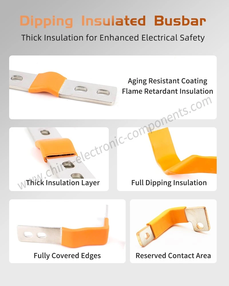
Value of Dip-Coated Copper Busbars in Electrical Systems
Overall, dip-coated copper busbars represent a mature process that combines electrical conductivity with protective insulation. Its core value extends beyond merely enhancing visual consistency; the continuous insulation layer reduces the risk of accidental contact-whether between conductors or between conductors and surrounding structures-while providing a degree of environmental and mechanical protection.
For energy storage systems, dip-coated busbars strike an optimal engineering balance between high-current transmission, electrical isolation, and efficient use of cabinet space. In the context of new energy vehicles, the choice of insulation method must further account for requirements regarding lightweight design, compactness, heat dissipation, and vibration durability. Final selection should be based on a comprehensive assessment of rated voltage, current-carrying capacity, operating temperature, insulation clearance, installation space, and environmental conditions, rather than relying solely on the insulation material or coating thickness.
From an engineering procurement perspective, when selecting plastic-coated copper busbars, key factors to verify include the copper grade and cross-section, the insulation material system, coating thickness tolerances, and the dimensions of the exposed ends. Capabilities for withstand voltage and environmental reliability testing, combined with customized verification based on product drawings, ensure compatibility with the installation and operational requirements of actual electrical systems.
contact us

Send Inquiry