










Manganin Copper Shunt Assemblies in Smart Meters and BMS Current Sensing
Sep 13, 2026
Leave a message
TCR ±15 ppm/°C: Why Manganin Copper Shunts Control Current-Sensing Error
A manganin copper shunt converts current into a measurable millivolt-level voltage by forcing the load current through a precisely defined resistance element. For smart meters and BMS current sensing, the resistance must remain stable as temperature, current density, mechanical stress, and assembly conditions change. A production-grade manganin shunt therefore combines a low-TCR Manganin resistance strip with high-conductivity copper terminals, rather than using copper alone.
The electrical relationship is straightforward:
V = I × R
Any change in R directly changes the measured voltage V. For a shunt carrying high current, the engineering problem is therefore not simply obtaining a low resistance value. It is controlling resistance drift caused by TCR, geometry, weld heat input, residual stress, and temperature rise.
Manganin CuMn12Ni: ±15 ppm/°C TCR After Stress Relief
Manganin is a copper-based resistance alloy designed for stable electrical resistance. A representative production condition uses Manganin with approximately 44 ± 0.5 μΩ·cm resistivity and a temperature coefficient of resistance around ±15 ppm/°C after annealing. Before stress-relief treatment, residual forming stress can produce higher resistance variation and a TCR around ±30 ppm/°C under the referenced process condition.
For a shunt with a nominal resistance of 100 μΩ, a 15 ppm/°C TCR corresponds to approximately:
ΔR/R = 15 × 10⁻⁶ /°C
Over a 100°C temperature change, the theoretical resistance shift attributable to TCR alone is approximately 0.15%, before considering thermal gradients, contact interfaces, material variation and mechanical effects.
C1100/T2 Copper: ≥97% IACS Conductive Terminal Path
The copper section carries the majority of the current outside the resistance element. High-conductivity copper reduces parasitic voltage drop and local Joule heating in the terminal region.
A typical Apollo manganin shunt construction uses high-conductivity copper terminals together with a manganin resistance strip. T2 copper can provide conductivity of approximately ≥97% IACS, while the manganin section supplies the controlled resistance required for current measurement.
The material roles should remain clearly separated:
| Functional region | Typical material | Primary requirement | Main engineering risk |
| Resistance element | Manganin / CuMn12Ni | Stable resistivity, low TCR | Resistance drift |
| Current terminal | T2/C1100 copper | ≥97% IACS conductivity | Excessive I²R heating |
| Transition joint | Cu-Manganin EBW | Metallurgical continuity | Heat-affected resistance shift |
| Stamped geometry | Copper + Manganin composite | ±0.01 mm dimensional control where specified | Springback and residual stress |
±0.01 mm Stamping Tolerance: Geometry Is an Electrical Parameter
A shunt's resistance is determined not only by alloy resistivity but also by the resistance-element geometry:
R = ρL/A
where:
ρ = material resistivity
L = effective resistance length
A = conductive cross-sectional area
This makes stamping accuracy an electrical-performance variable.
For a precision shunt, dimensional changes in the resistance section can modify the final resistance value even when the Manganin material itself remains within specification. Progressive stamping therefore requires control of blanking clearance, bending radius, strip alignment, springback and burr height.
Where the customer drawing specifies ±0.01 mm, dimensional inspection should be performed against the actual functional datum rather than relying only on nominal press settings.
300–350°C Stress Relief: Controlling Residual Stress Before Final Resistance Testing
Stamping and electron-beam welding introduce localized thermal and mechanical stress. For Manganin shunts, stress-relief annealing can stabilize dimensions and resistance.
A referenced production process uses approximately 300–350°C annealing, with holding time adjusted according to material thickness and component geometry. After treatment, representative material data show resistivity changing from approximately 48 ± 2 μΩ·cm to 44 ± 0.5 μΩ·cm, while tensile strength changes from approximately 520–580 MPa to 420–450 MPa.
The exact annealing curve must be qualified against the alloy grade, strip thickness, stamped geometry, and required resistance specification. The process objective is not simply softening the material; it is reducing residual stress without producing unacceptable dimensional change or electrical drift.

EBW Cu-Manganin Joints: Heat Input, Vacuum and Metallurgical Stability
Electron Beam Welding (EBW) is particularly suitable for copper-manganin shunts because the process can concentrate energy into a narrow weld zone while operating in a vacuum environment. This is important when the resistance element must remain dimensionally stable, and the transition between conductive copper and resistive Manganin must maintain low parasitic resistance.
Apollo's manganin shunt production route combines electron-beam welding, precision stamping, heat treatment, and ultrasonic cleaning for current-sensing components used in metering applications.
Vacuum EBW: Controlled Energy Density for Cu-Manganin Dissimilar Metals
Copper has high thermal conductivity, while Manganin has substantially higher electrical resistivity. During welding, the different thermal responses of the two materials affect penetration, molten-pool stability, and the width of the heat-affected region.
The EBW qualification plan should therefore control:
Accelerating voltage and beam power according to material thickness and joint design.
Beam focus position relative to the Cu-Manganin interface.
Travel speed to control linear heat input.
Beam oscillation, where required by joint geometry.
Vacuum level to maintain a stable electron beam.
Joint fit-up and overlap before welding.
Post-weld resistance across the functional current path.
The correct parameter window is part-specific. Copying beam current or travel speed from another shunt geometry does not constitute process qualification.
Cross-Section Metallography: Weld Penetration and Porosity Control
A qualified EBW process should be verified through metallographic cross-sections rather than visual inspection alone.
The inspection should evaluate:
| Inspection item | Engineering purpose | Typical verification method |
| Fusion continuity | Confirm metallurgical joining | Metallographic cross-section |
| Penetration profile | Verify designed joint depth | Cross-section measurement |
| Porosity | Identify internal weld defects | Metallography / X-ray where required |
| Cracks | Detect weld-induced discontinuities | Microscopy |
| HAZ condition | Check thermal influence | Metallographic examination |
| Electrical resistance | Confirm functional current path | Four-wire micro-ohm measurement |
| Mechanical integrity | Verify joint strength | Tensile / shear/pull test |
For precision current sensing, the weld is part of the electrical circuit. A mechanically acceptable weld can still be electrically unacceptable if the transition zone introduces unstable resistance.
Four-Wire Resistance Measurement: Separating Shunt Resistance from Lead Error
For micro-ohm or sub-milliohm shunts, two-wire resistance measurement can introduce substantial lead and contact resistance error.
A four-wire Kelvin measurement separates current delivery from voltage measurement:
Force current → Shunt → Force return
Sense voltage → Resistance element → Sense return
This allows the measurement system to capture the voltage drop across the specified electrical datum rather than the resistance of the test leads and contact interfaces.
For production QA, the test fixture should define:
Current magnitude.
Stabilization time.
Voltage-sense location.
Ambient or controlled temperature.
Resistance acceptance window.
Measurement-system resolution and GR&R requirement.
EBW vs Resistance Brazing: Which Joint Process Fits a Precision Shunt?
| Parameter | Electron Beam Welding | Resistance Silver Brazing |
| Heat input | Highly localized | Broader thermal influence |
| Environment | Vacuum | Controlled atmosphere/flux/furnace depending on process |
| Filler metal | None | Silver-based filler normally required |
| Joint geometry | Suitable for focused Cu-Manganin transition | Suitable for broader brazed interfaces |
| HAZ control | Strong process capability when qualified | Depends heavily on thermal cycle |
| Electrical transition | Direct metallurgical joint | Depends on braze layer |
| Post-process cleaning | Low contamination potential | Flux/filler management may be required |
| Typical application logic | Precision shunt and dissimilar-metal current path | Larger-area brazed electrical assemblies |
EBW is normally selected when the design requires a controlled Cu-Manganin transition with limited thermal influence. Resistance silver brazing remains useful when joint geometry, production volume, or filler-metal design favors a brazed structure.
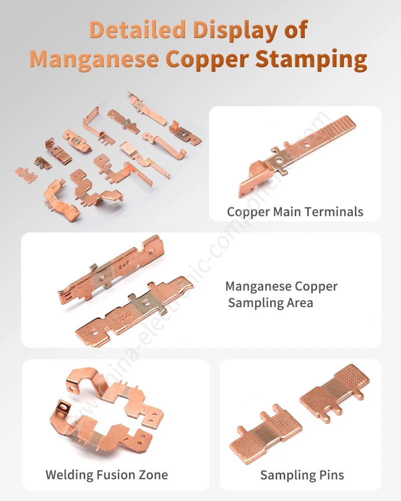
±0.01 mm Stamping and 300–350°C Annealing: From Composite Strip to Finished Shunt
The manufacturing sequence must be designed around the electrical function of the finished component. Welding, stamping, and heat treatment cannot be treated as independent operations because each process can alter the resistance value and dimensional stability.
Precision Stamping at ±0.01 mm: Burr, Springback and Current Density
Composite Cu-Manganin strips require controlled feeding and positioning before progressive stamping.
The process window should address:
Strip flatness before forming.
Material thickness tolerance.
Punch-to-die clearance.
Burr height and direction.
Bending radius.
Progressive station alignment.
Springback after forming.
Final resistance-element length.
A burr on the resistance section can alter the effective cross-sectional area. Excessive burrs can also interfere with automated assembly or create localized stress concentrations.
For automated meter assembly, dimensional inspection can include optical measurement, pin gauges, height gauges and CMM inspection depending on geometry and tolerance requirements.
300–350°C Annealing: Resistance Stability After Forming
Heat treatment should be positioned according to the process sequence.
A typical route can be structured as:
Manganin/Copper preparation → EBW → Precision stamping → Stress-relief annealing → Cleaning → Dimensional inspection → Resistance testing → Final inspection
An alternative sequence may be required for specific geometries. The selected route should be established through process validation because post-weld stamping and post-stamping annealing produce different residual-stress conditions.
Ultrasonic Cleaning and Surface Control: Electrical Contact Reliability
Ultrasonic cleaning removes stamping oils, metallic particles, and process residues before final inspection.
For current-sensing assemblies, cleaning quality affects more than appearance. Residues can interfere with subsequent electrical contact, soldering, brazing, or encapsulation processes.
A controlled cleaning process should define:
Cleaning chemistry.
Bath temperature.
Ultrasonic frequency and power.
Cleaning duration.
Rinse-water quality.
Drying temperature.
Surface inspection criteria.
CMM Inspection and Resistance Testing: Two Different Quality Gates
Dimensional conformity does not prove electrical conformity.
A shunt can pass dimensional inspection while failing resistance because of:
Manganin material variation.
Weld-zone resistance variation.
Heat-treatment drift.
Effective resistance-length variation.
Cross-sectional variation.
Measurement-temperature differences.
The production control plan should therefore maintain separate dimensional and electrical inspection characteristics.
Download Shunt Design Specification
100A Smart Meter Shunts: Current Sensing Without Excessive Thermal Drift
Smart meters commonly use shunts to convert load current into a measurable voltage signal. A representative design may be specified for 100A single-phase metering, where the resistance value must remain stable enough to maintain measurement accuracy over the meter's operating temperature range. Apollo's 100A manganin shunt design combines a copper substrate and manganese-copper strip through electron-beam welding, followed by stamping, heat treatment, and cleaning.
Smart Meter Shunt Resistor: Copper Carries Current, Manganin Defines Resistance
The composite structure provides functional separation:
Copper section → High-current conduction
Manganin section → Precision resistance
EBW interface → Electrical and mechanical transition
This architecture avoids making the entire current path from a high-resistivity alloy while avoiding the excessive temperature coefficient associated with using ordinary copper as the sensing element.
For procurement engineers, the drawing should define the electrical datum clearly. A resistance specification without a defined measurement temperature, current, sense-point location, and stabilization condition can produce inconsistent supplier results.
100A Current Path: Joule Heating Must Be Included in the Measurement Model
Shunt power follows:
P = I²R
At 100A, even a very small resistance produces measurable heat.
For example, a 100 μΩ shunt dissipates:
P = 100² × 100 × 10⁻⁶ = 1 W
A 50 μΩ shunt dissipates:
P = 0.5 W
This heat raises the shunt temperature above ambient. The resulting temperature rise then changes resistance according to the material's TCR.
This creates a closed electrical-thermal relationship:
Current → Joule heating → Temperature rise → Resistance change → Measurement error
The shunt must therefore be evaluated as an electrothermal component rather than as a simple resistor.
Smart Meter Assembly: Contact Geometry and Relay Integration
In magnetic latching relay systems, the shunt can be integrated into the current path while providing the voltage signal required for current measurement.
Apollo's latching relay component range includes copper-Manganin shunt terminals manufactured through electron-beam welding and precision stamping for current sensing and overload monitoring.
The interface design should consider:
Terminal width and thickness.
Mounting-hole position.
Current direction.
Kelvin-sense location.
Clearance from heat-sensitive components.
Relay terminal geometry.
Automated assembly datum.
Final resistance after assembly.
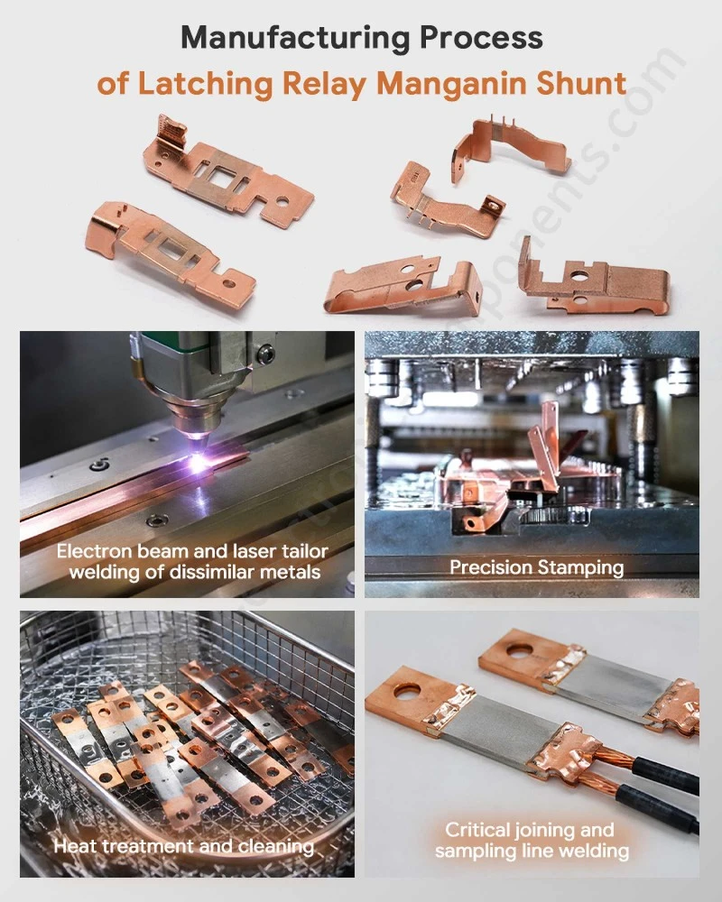
BMS Current Sensing at ±15 ppm/°C: Material and Process Selection
Battery Management Systems require current information for charge control, discharge monitoring, overcurrent protection, and state estimation. Shunt-based current sensing is attractive when the electrical architecture requires a direct current path with a measurable voltage drop.
The same material principle applies to BMS applications: the copper section handles high current while the Manganin section establishes the sensing resistance.
Current Sensing Copper Busbar vs Manganin Shunt: Different Electrical Functions
| Component | Primary function | Material priority | Resistance requirement |
| Copper busbar | High-current conduction | High conductivity | As low as practical |
| Manganin shunt | Current measurement | Low and stable TCR | Precisely controlled |
| Laminated busbar | Power distribution + insulation | Copper + dielectric system | Low parasitic impedance |
| Copper-Manganin shunt assembly | Current conduction + measurement | Controlled composite structure | Defined milliohm/μΩ range |
A conventional copper busbar is designed to minimize voltage drop. A shunt deliberately introduces a controlled resistance so that the resulting voltage can be measured.
Therefore, replacing a manganin shunt with a standard copper busbar does not solve the same engineering problem.
C1100 Copper vs Manganin: Material Selection at 97%+ IACS
| Property | C1100/T2 Copper | Manganin |
| Main role | Current conduction | Current measurement |
| Electrical conductivity | Typically ≥97% IACS for specified T2 material | Much lower than copper |
| Resistivity | Low | Approximately 44–48 μΩ·cm under referenced conditions |
| TCR | Higher than precision resistance alloys | Approximately ±15 ppm/°C after referenced annealing |
| Thermal conductivity | High | Lower |
| Forming | Good | Requires controlled forming |
| Typical shunt location | Terminal/current path | Resistance element |
The correct material decision is therefore functional rather than based solely on conductivity.
BMS Shunt Qualification: Resistance, Temperature and Mechanical Stress
For a production BMS shunt, validation should include electrical and mechanical conditions rather than resistance measurement at room temperature alone.
A suitable qualification plan can include:
Initial resistance measurement.
Resistance-temperature characterization.
High-current temperature-rise testing.
Thermal cycling.
Mechanical pull/shear testing of the Cu-Manganin joint.
Metallographic weld inspection.
Dimensional inspection.
Post-test resistance measurement.
Correlation between resistance drift and temperature history.
Where required by the customer's quality system, these characteristics should be incorporated into the Control Plan, PFMEA, MSA, and PPAP documentation under IATF 16949 production controls.

PPAP Level 3 and ±0.01 mm Control: What Procurement Should Specify
For Tier 1 automotive and energy-storage programs, a shunt drawing should define measurable acceptance criteria rather than relying on phrases such as "high precision" or "stable resistance."
A practical RFQ package should identify:
| RFQ parameter | Example engineering requirement |
| Resistance | Customer-defined μΩ / mΩ nominal value |
| Resistance tolerance | Customer drawing specification |
| TCR | Example ±15 ppm/°C |
| Operating current | Example 100A |
| Measurement temperature | Defined reference temperature |
| Copper grade | T2 / C1100 or approved equivalent |
| Manganin grade | Customer-approved resistance alloy |
| Dimensional tolerance | Example ±0.01 mm |
| Weld process | EBW |
| Heat treatment | Qualified stress-relief process |
| Inspection | CMM + electrical resistance test |
| Quality system | IATF 16949 |
| Submission package | PPAP Level 3 where specified |
PPAP Level 3: Traceability From Raw Material to Resistance Test
For an automotive or energy-storage program, the supplier should be able to connect:
Raw material lot → strip processing → EBW batch → stamping batch → annealing batch → inspection record → resistance result → finished-part lot
This is more useful than simply supplying a final inspection certificate.
Material certificates should identify alloy grade, thickness, relevant mechanical/electrical properties, and lot information. Welding records should identify the qualified equipment and process parameters. Final resistance records should remain traceable to the production lot.
GR&R and Resistance Measurement: Measurement System Before Mass Production
A resistance specification is only meaningful when the measurement system has adequate repeatability and reproducibility.
For low-resistance shunts, the MSA plan should address:
Kelvin connection repeatability.
Probe pressure.
Probe position.
Test current.
Temperature stabilization.
Instrument resolution.
Operator variation.
Fixture variation.
A measurement system capable of displaying six decimal places is not automatically accurate enough. Resolution, bias, repeatability and reproducibility must be evaluated against the actual tolerance.
Manganin Copper Shunt Supplier Selection: 7 Engineering Checks for OEM Production
When qualifying a manganin copper shunt supplier, procurement should evaluate manufacturing capability together with material and measurement control.
97% IACS Copper and ±15 ppm/°C Manganin: Verify the Material System
Confirm:
Copper grade and conductivity.
Manganin alloy grade.
Strip thickness tolerance.
Resistivity range.
TCR requirement.
Material lot traceability.
EBW Cross-Section and μΩ Resistance: Verify the Weld Qualification
Request evidence of:
Metallographic cross-sections.
Weld penetration evaluation.
Porosity/crack inspection.
Mechanical joint testing.
Initial and post-aging resistance measurements.
±0.01 mm Stamping and CMM: Verify Dimensional Capability
The supplier should demonstrate measurement capability against the customer's actual drawing datums. Critical dimensions should be connected to the electrical function of the shunt.
300–350°C Stress Relief: Verify Heat-Treatment Control
The supplier should provide the qualified temperature range, time window, loading method, atmosphere requirements where applicable and post-treatment verification method.
100A Current Loading: Verify Thermal Performance
The supplier should evaluate temperature rise under the customer's specified current, mounting condition and ambient temperature. A free-air test and an assembled-meter test may produce materially different thermal results.
IATF 16949 and PPAP Level 3: Verify Automotive Quality Readiness
For automotive BMS programs, the supplier should be capable of supporting drawing review, DFM, PFMEA, Control Plan, MSA, process capability studies, and PPAP documentation according to the customer's submission requirements.
Prototype-to-Volume Consistency: Verify Process Transfer
A T1 prototype that meets resistance requirements does not prove production capability. The supplier should demonstrate that the same EBW, stamping, and annealing process windows can be transferred into serial production without changing the resistance distribution.
Engineering Summary: ±15 ppm/°C TCR, EBW and ±0.01 mm Control
Manganin copper shunt assemblies are composite electrical components in which material selection, weld metallurgy, stamping geometry, heat treatment, and resistance measurement are directly coupled.
The preferred engineering structure is:
High-conductivity copper → high-current conduction
Manganin → controlled resistance and low TCR
EBW → localized Cu-Manganin metallurgical joint
Precision stamping → controlled electrical geometry
300–350°C stress relief → reduced residual-stress influence
Four-wire measurement → controlled resistance verification
For smart meters, the target is stable current measurement across the operating temperature range. For BMS applications, the same architecture can provide a defined voltage signal while maintaining a controlled high-current path.
The supplier's value should therefore be assessed through measurable process capability: material traceability, EBW cross-section quality, dimensional capability, TCR verification, resistance measurement, thermal testing, and production traceability-not through generic claims of precision.
FAQ
What information should be provided when requesting a custom manganin copper shunt quotation?
Provide the nominal resistance, resistance tolerance, maximum current, operating temperature, copper and Manganin grades, strip thickness, critical dimensions, Kelvin-sense points, welding requirements, and annual volume. A drawing or sample enables DFM review before quotation.
Can a manganin shunt supplier provide PPAP Level 3 documentation for automotive BMS production?
Yes, when the supplier operates an automotive quality system and the project requires PPAP Level 3. The submission can include dimensional results, material certificates, process documentation, MSA, PFMEA, Control Plan, and capability data according to the customer's requirements.
How is the resistance stability of an EBW Manganin shunt verified after welding?
Resistance is measured after welding and subsequent heat treatment using a defined four-wire method. Qualification should also correlate resistance drift with metallographic weld inspection, thermal cycling, and high-current temperature-rise testing.
contact us

Send Inquiry