










Sourcing Stainless Steel Studs and Custom Metal Fasteners for Electrical Cabinets and Enclosures
Oct 04, 2026
Leave a message
Electrical cabinet studs are load-bearing threaded interfaces that secure copper busbars, transformer brackets, terminal blocks, insulation supports, grounding components, and enclosure assemblies. For cabinet hardware exposed to vibration, humidity, thermal cycling, or repeated assembly, material selection and thread forming directly affect pull-out strength, torque resistance, corrosion performance, and long-term electrical clearance.
304/316 stainless steel, brass, and cold-rolled thread profiles should therefore be specified according to load, environment, torque, and mating-material requirements rather than nominal thread size alone.
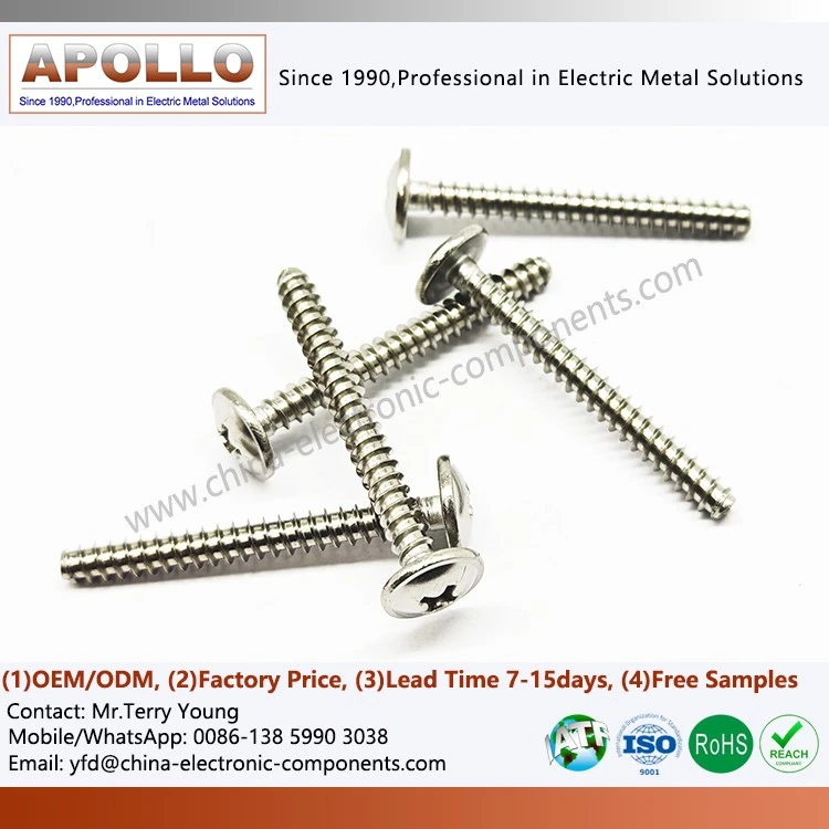
304/316 Stainless Steel Studs for Electrical Cabinets: Load and Corrosion Requirements
A stainless steel stud used inside a power distribution cabinet performs two mechanical functions: it transfers clamping force into the enclosure structure and maintains a stable threaded interface during service.
For stainless steel studs in electrical applications, 304 stainless steel is normally considered when the cabinet operates in an indoor or controlled industrial environment. 316 stainless steel becomes more relevant where chloride exposure, condensation, coastal atmosphere, or aggressive industrial environments increase the corrosion load.
| Property / Requirement | 304 Stainless Steel | 316 Stainless Steel | Engineering Consideration |
| Typical application | Indoor electrical cabinets | Outdoor/humid / chloride-exposed cabinets | Select according to environment |
| Corrosion resistance | Good | Higher, especially against chlorides | 316 contains Mo |
| Magnetic response | Generally low | Generally low | Depends on processing conditions |
| Thread forming | Suitable | Suitable | Tooling must account for work hardening |
| Surface condition | Passivated / untreated | Passivated / untreated | Passivation improves corrosion resistance |
| Typical fastening role | Busbar supports, brackets, terminal structures | Outdoor ESS/PV cabinets, exposed enclosures | Confirm environmental requirements |
| Assembly concern | Galling possible | Galling risk can be higher | Control torque and lubrication strategy |
For high-volume electrical hardware, material certification should identify the actual grade rather than simply specifying "stainless steel." A purchase specification can include 304 or 316 grade, mechanical property requirements, surface treatment, thread specification, dimensional tolerance, and inspection method.
M5–M12 Stainless Steel Stud Dimensions and ±0.01 mm Inspection Control
Stud geometry should be controlled across more than the nominal thread diameter. The effective assembly interface includes:
M5–M12 thread sizes: Select according to clamping force, available installation space, and current-carrying component geometry.
Thread pitch: Match the nut or threaded component precisely; M5, M6, M8, and M10 coarse threads are common industrial configurations.
Thread length: Define the effective engagement length rather than overall stud length.
Shoulder diameter: Control the transition between threaded and unthreaded sections where a positioning function is required.
Flatness and perpendicularity: Relevant when the stud supports a busbar or rigid electrical component.
Dimensional tolerance: Critical locating dimensions can be controlled to ±0.01 mm where the assembly requires precision positioning.
Surface condition: Burrs, rolled-thread defects, and sharp transitions should be removed before final inspection.
For cabinet assemblies, the stud should not be evaluated independently from the mating nut, busbar terminal, bracket, washer, and enclosure material. Thread engagement, clamp load, and contact geometry form one mechanical system.
C1100, C2680, 304 and 316: Material Selection by Electrical and Mechanical Load
Stainless steel is mechanically suitable for many fastening structures, but it is not normally selected as the primary high-current conductor. Copper and copper alloys provide substantially higher electrical conductivity.
For electrical cabinets containing copper busbars, the fastening system should therefore separate the mechanical fastening function from the current-carrying function unless the stud is intentionally designed as an electrical conductor.
| Material | Main Characteristic | Typical Electrical Role | Typical Fastener Role | Main Engineering Concern |
| C1100 / C11000 Copper | High conductivity | Busbars, terminals | Limited structural fastening | Lower mechanical strength |
| C2680 Brass | Good machinability and conductivity | Terminals, conductive hardware | Studs, inserts, terminals | Lower corrosion resistance than stainless in some environments |
| 304 Stainless Steel | Corrosion-resistant structural material | Generally non-current-carrying | Cabinet studs, brackets, supports | Lower conductivity |
| 316 Stainless Steel | Enhanced chloride resistance | Generally non-current-carrying | Outdoor/ESS/PV fastening | Higher material cost and galling risk |
A common design architecture is therefore:
C1100 copper busbar → conductive terminal interface → 304/316 stainless steel mechanical stud → washer/nut → cabinet support structure.
This arrangement allows the current path and mechanical load path to be engineered separately.
304/316 Stainless Steel vs C2680 Brass: Torque and Conductivity Trade-Off
The choice between stainless steel and brass should not be based solely on tensile strength. For electrical hardware, conductivity, galvanic compatibility, corrosion conditions, thread friction, and assembly torque all affect the final design.
| Design Parameter | 304/316 Stainless Steel | C2680 Brass |
| Structural fastening | Strong candidate | Suitable for moderate loads |
| Electrical conductivity | Low relative to copper/brass | Significantly higher |
| Corrosion resistance | High | Good, depending on environment |
| Thread galling | Requires attention | Generally lower concern |
| Current-carrying application | Usually not preferred | More suitable |
| Cabinet support application | Strong candidate | Suitable where conductivity is useful |
| Outdoor chloride environment | 316 preferred | Requires environmental evaluation |
| Weight | Higher than aluminum | Higher than aluminum |
| Machining/forming consideration | Work hardening | Generally easier to machine/form |
When a stud is mounted close to a copper busbar, galvanic compatibility should also be considered. Surface treatment, washers, plating, moisture exposure, and enclosure sealing can influence long-term interface stability.
ISO 9227 and Salt-Spray Verification for Outdoor Electrical Hardware
For outdoor PV and ESS enclosures, corrosion validation should be linked to the actual environmental specification rather than relying on a generic "stainless" designation.
Relevant verification can include:
ISO 9227: Salt spray corrosion testing where specified by the customer.
Material certificate: Verification of 304/316 stainless steel grade.
Surface inspection: Check for scratches, contamination, and thread damage after finishing.
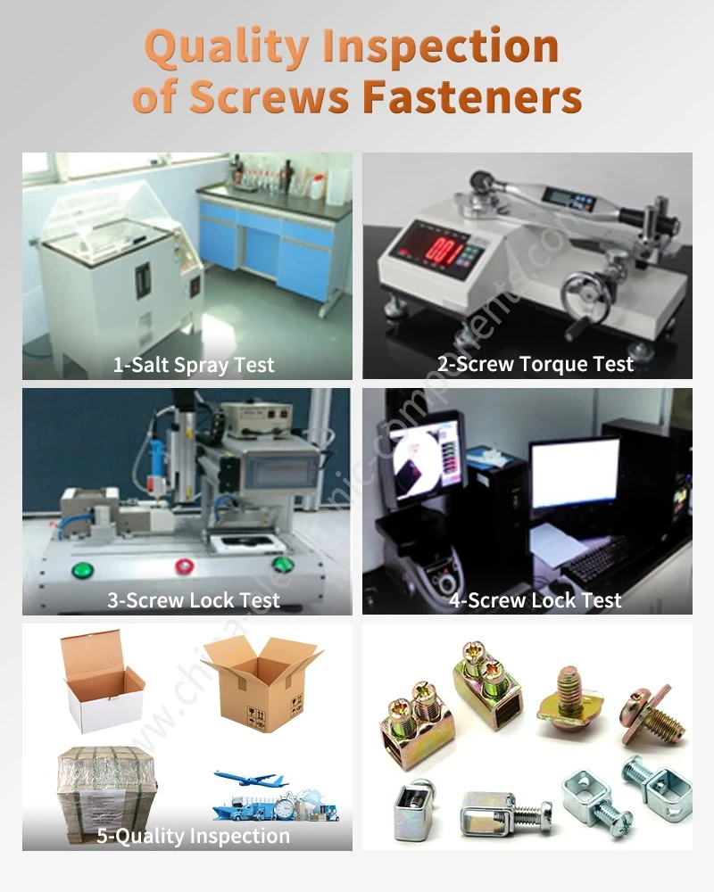
Thread gauge inspection: GO/NO-GO gauge verification for production threads.
Torque testing: Confirm assembly torque and thread integrity.
Visual corrosion inspection: Record corrosion morphology after environmental testing.
The exact salt-spray duration should be defined by the customer's product specification rather than treating one exposure period as a universal qualification value.
Request Free DFM Evaluation & Quote
Cold-Rolled Threads: M6–M10 Torque Resistance and Pull-Out Performance
For production stainless steel studs, the thread manufacturing method directly affects the surface structure and mechanical behavior of the threaded section.
Cold thread rolling forms the thread profile by plastic deformation rather than removing material through conventional cutting. The process can increase surface hardness and preserve material continuity around the thread profile.
For custom electrical fastener supplier projects, cold-rolled threads are particularly useful when the customer requires stable thread geometry across large production batches.
M6–M10 Cold-Rolled Threads and Work-Hardened Surface Structure
During thread rolling, hardened dies force the stainless steel blank into the required thread geometry.
The main process variables include:
Blank diameter: Must be matched to thread specification and material flow.
Rolling force: Excessive force can damage tooling or distort the stud.
Die alignment: Poor alignment can produce uneven thread profiles.
Material hardness: Stainless steel work-hardening behavior must be considered.
Rolling speed: Must remain stable to maintain repeatable forming.
Thread flank geometry: Directly affects nut engagement and torque behavior.
Surface condition: Rolled threads should be free from tearing, folds, and visible cracks.
Unlike a cut thread, a properly formed rolled thread does not remove a continuous helical chip from the thread profile. The resulting material flow can improve thread surface integrity and fatigue behavior, provided that the forming parameters are correctly controlled.
ISO Metric Thread Gauging and Torque Testing for M6–M10 Studs
Thread dimensional inspection should combine gauge inspection with functional assembly testing.
| Inspection | Purpose | Typical Control Method |
| Thread pitch | Confirm mating compatibility | Optical measurement/thread gauge |
| Major diameter | Verify thread envelope | Micrometer / optical system |
| Thread profile | Detect forming defects | Optical inspection |
| GO gauge | Verify functional thread acceptance | GO/NO-GO gauge |
| NO-GO gauge | Prevent acceptance of oversized threads | GO/NO-GO gauge |
| Torque test | Evaluate resistance during assembly | Calibrated torque equipment |
| Pull-out test | Measure axial fastening resistance | Tensile test fixture |
| Surface inspection | Identify folds/cracks/burrs | Visual / microscope inspection |
The exact torque and pull-out limits should be defined from the selected material, thread size, engagement length, substrate thickness, nut grade and customer assembly specification. A universal torque value for every stainless steel stud would be technically inappropriate.
±0.01 mm CMM Inspection for Custom Stud Geometry
When a stud contains a non-standard shoulder, locating pin, flange, or offset section, dimensional inspection should move beyond conventional thread gauges.
A CMM inspection can verify:
Overall length
Thread-to-shoulder concentricity
Shoulder diameter
Stud perpendicularity
Head or flange geometry
Hole-to-axis position
Critical locating dimensions
Formed geometry after secondary operations
For high-volume programs, critical dimensions can be monitored using SPC rather than relying exclusively on final inspection. This creates a process-control loop between tooling wear, dimensional drift, and corrective action.
In-Die Riveting and Laser Welding: Integrating Studs with Electrical Terminals
A cabinet hardware program can involve more than standalone studs. In many electrical assemblies, the actual requirement is a combined component such as a stamped copper terminal + stainless steel stud + conductive interface.
This changes the manufacturing strategy.
Instead of sourcing a stamped terminal from one supplier and a fastener from another, the manufacturer can integrate stamping, forming, riveting, welding, and final inspection into one controlled production route.
C1100/C2680 Stamping + In-Die Riveting for Electrical Terminals
Precision metal stamping is suitable for copper and brass terminals requiring repeatable geometry and high-volume production.
A typical process can include:
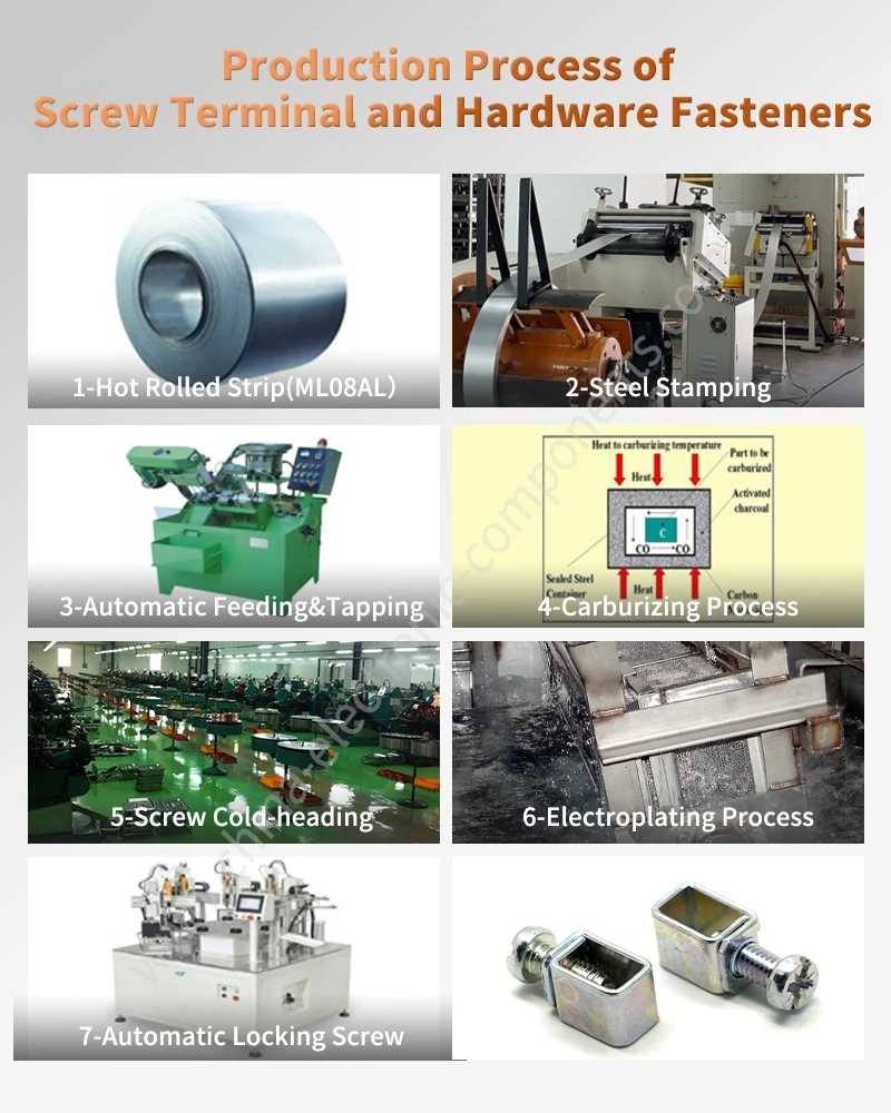
Coil feeding → straightening → progressive stamping → bending/forming → in-die riveting → thread/stud integration → surface treatment → dimensional inspection → electrical testing → packaging.
Key controls include:
C1100/C11000 copper: Used where high electrical conductivity is required.
C2680 brass: Used where conductivity and mechanical formability must be balanced.
In-die riveting: Reduces separate assembly operations and maintains positional repeatability.
Progressive die: Suitable for high-volume terminal production.
Dimensional tolerance: Critical interfaces can be controlled to ±0.01 mm where specified.
CMM inspection: Used for complex three-dimensional stamped components.
Visual inspection: Detects cracks, burrs, deformation, and surface damage.
The result is not simply a faster assembly process. The main engineering benefit is control over the positional relationship between the conductive terminal and mechanical fastening interface.
Resistance Silver Brazing and Laser Welding for Copper Electrical Assemblies
Different joining technologies should be selected according to material combination, thermal input, and required joint geometry.
| Joining Process | Typical Application | Main Advantage | Main Risk / Control Point |
| In-die riveting | Copper/brass terminal + mechanical fastener | High-volume repeatability | Rivet height and joint force |
| Resistance welding | Conductive metal assemblies | Localized heating | Electrode force/current control |
| Resistance silver brazing | Copper/contact assemblies | Conductive bonded joint | Filler distribution and thermal cycle |
| Laser welding Cu-Cu | Copper busbar assemblies | Low mechanical deformation | High reflectivity and heat control |
| Laser welding Cu-Al | Dissimilar conductive components | Localized heat input | Intermetallic formation and weld penetration |
| Molecular diffusion welding | High-reliability laminated conductive assemblies | Solid-state bonding | Surface preparation and pressure |
For copper-to-aluminum joints, laser welding Cu-Al requires particular control of energy density, beam position and intermetallic compound formation. The weld cross-section should be inspected when joint reliability is a critical design requirement.
ISO 9001, IATF 16949 and PPAP Level 3 Documentation for Custom Fasteners
Automotive and energy-storage programs frequently require a documented quality package rather than dimensional inspection alone.
A production submission can include:
IATF 16949: Automotive quality management framework where applicable.
PPAP Level 3: Submission package when specified by the customer.
Dimensional report: Critical and major characteristics.
Material certificate: Stainless steel, copper, or brass grade verification.
Process Flow Diagram: Manufacturing route from raw material to final inspection.
PFMEA: Process-related risk analysis.
Control Plan: Production-stage control requirements.
MSA: Measurement-system evaluation where required.
Capability study: Cp/Cpk or equivalent statistical analysis for designated characteristics.
For a custom electrical fasteners supplier, this documentation is particularly important when the stud becomes part of an electrical safety-related assembly.
Stainless Steel Stud + Stamped Terminal: One-Supplier Procurement Model
A combined procurement model becomes practical when the electrical cabinet assembly contains multiple precision metal components with tight positional relationships.
For example:
C1100 copper terminal + 304 stainless steel stud + stamped locating feature + in-die riveted connection
can be manufactured and inspected as one assembly rather than several separately purchased parts.
±0.01 mm Terminal-to-Stud Position Control in Integrated Assemblies
The main advantage is geometric control.
When a terminal and stud are purchased separately, the final assembly tolerance becomes the accumulated result of:
Terminal tolerance + stud tolerance + fixture tolerance + assembly clearance + operator/process variation.
When these components are integrated during production, the manufacturer can establish one datum system for the complete assembly.
This is particularly useful for:
Copper busbar fastening: Stud position must align with busbar holes.
Transformer mounting: Stud pitch must match the transformer bracket.
Terminal block assemblies: Thread axis must remain perpendicular to the mounting plane.
ESS power cabinets: Multiple high-current terminals require consistent spacing.
PV inverter cabinets: Conductive terminals and mechanical mounting interfaces must remain within enclosure clearance limits.
100% Visual Inspection and CMM Verification for Electrical Fastener Assemblies
Inspection strategy should reflect the risk level of the final application.
| Characteristic | Recommended Verification |
| Material grade | Material certificate / PMI where specified |
| Thread | GO/NO-GO gauge |
| Critical dimensions | CMM / optical measurement |
| Stud position | CMM / dedicated fixture gauge |
| Riveted joint | Height, diameter, joint force |
| Welded joint | Visual + metallographic inspection where required |
| Surface coating | Thickness measurement |
| Corrosion resistance | Environmental testing according to specification |
| Electrical continuity | Resistance measurement where applicable |
| Packaging | Visual and traceability inspection |
For precision electrical assemblies, CMM inspection should be linked to the product datum structure defined on the engineering drawing. Measuring isolated dimensions without controlling the functional datum relationship can produce a technically correct report that does not guarantee assembly fit.

M6–M10 Fastener Selection Matrix for EV, ESS, PV and Power Cabinets
The correct stud configuration depends on mechanical load, electrical architecture, environment, and assembly process.
EV/ESS/PV Cabinet Fastener Selection by Material and Environment
| Application | Recommended Stud Material | Terminal Material | Main Requirement | Typical Verification |
| Indoor distribution cabinet | 304 SS | C1100 / C2680 | Mechanical stability | Thread + dimensional inspection |
| Outdoor ESS cabinet | 316 SS | C1100 | Corrosion resistance | Environmental + dimensional testing |
| PV inverter enclosure | 316 SS / suitable coated grade | C1100/C2680 | Humidity and thermal cycling | Corrosion + torque testing |
| Transformer support | 304/316 SS | Steel/Copper interface | Mechanical load | Pull-out + dimensional testing |
| EV high-voltage assembly | Application-specific | C1100/C11000 | Electrical clearance and mechanical retention | Electrical + mechanical validation |
| Battery/ESS power terminal | 304/316 SS | C1100/C11000 | Low-resistance conductive interface | Contact resistance + torque validation |
The stud itself should not be treated as an isolated commodity. Its specification should be derived from the complete assembly drawing and environmental requirements.
PPAP Level 3 and Traceability: Quality Controls for Production Fasteners
For automotive and energy-storage customers, traceability should connect the raw material lot to the finished component.
A practical traceability structure can include:
Material heat/lot number: Links each production batch to its stainless steel or copper source.
Tooling identification: Records the progressive die or thread-rolling die used for production.
Production date and shift: Supports investigation of dimensional drift.
Inspection record: Links critical dimensions to the production lot.
Torque/pull-out results: Provides mechanical verification for designated characteristics.
Surface-treatment record: Identifies coating/passivation process parameters.
Packaging identification: Prevents mixed-lot delivery.
PPAP Level 3 documentation: Supports customer approval for automotive programs.
For high-volume programs, the control plan should identify characteristics that directly influence cabinet assembly, including thread quality, stud position, flange geometry, and terminal-to-stud alignment.
Frequently Asked Questions: M6–M10 Stainless Steel Electrical Stud Procurement
What is the typical lead time for PPAP Level 3 stainless steel electrical studs?
For a new custom stud, lead time depends on tooling complexity, material availability, sample requirements, and PPAP scope. A typical project should separate tooling, T1 sampling, validation, and mass-production approval rather than treating them as one delivery stage.
How is the service life of a custom stainless steel stud die evaluated?
Tool life is monitored through dimensional drift, thread profile condition, burr formation, and production stroke count. Preventive maintenance should be triggered by defined process limits rather than waiting for visible tooling failure.
How is the coating or plating thickness of custom electrical fasteners verified?
Coating thickness can be verified using X-ray fluorescence (XRF), magnetic or eddy-current methods depending on the substrate and coating system. The measurement method and acceptance range should be specified on the drawing or quality standard.
Engineering Procurement Checklist for M6–M12 Custom Metal Fasteners
Before placing a production order for threaded metal studs China sourcing, provide the supplier with:
Material grade: 304, 316, C2680, C1100, or customer-specified equivalent.
Thread specification: M5–M12, pitch, tolerance class, and effective engagement length.
Critical dimensions: Identify dimensions requiring ±0.01 mm control.
Surface treatment: Passivation, plating, coating, or untreated condition.
Environmental requirement: Indoor, outdoor, ESS, PV, EV, or specified corrosion environment.
Mechanical test: Torque, pull-out, tensile, or joint-force requirement.
Electrical requirement: Conductivity/contact resistance where the component participates in the current path.
Inspection requirement: CMM, thread gauge, optical inspection, or dedicated gauges.
Quality documentation: IATF 16949, PPAP Level 3, material certificates and dimensional reports where required.
Assembly integration: Specify whether the requirement includes stamped terminals, riveting, welding, or other secondary operations.
For electrical cabinet and enclosure programs, the most useful sourcing model is not simply purchasing a lower-cost threaded component. It is defining the material, thread-forming process, positional tolerance, joining method, inspection system, and traceability requirements as one engineered component specification.
For projects requiring stainless steel studs, electrical stamped copper terminals, custom electrical fasteners, or integrated metal assemblies, Apollo Electronic Components can evaluate the drawing, material combination, fastening interface, and production route before tooling release.
contact us
Send Inquiry