



AgFe vs. AgNi Electrical Contacts: Fine-Grain Microstructure for Low-Current Inductive DC Switching
Oct 31, 2026
Leave a message
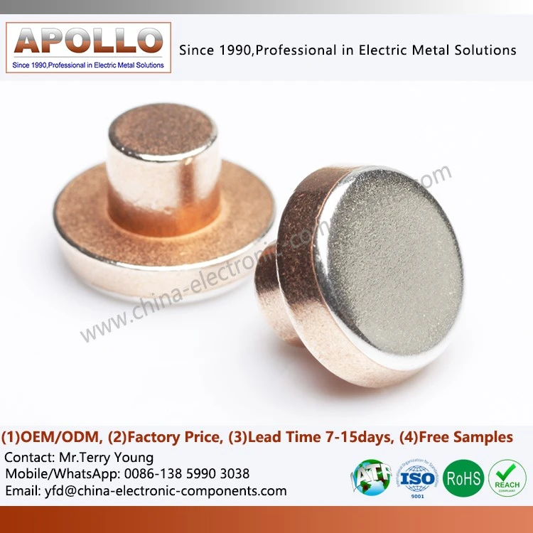
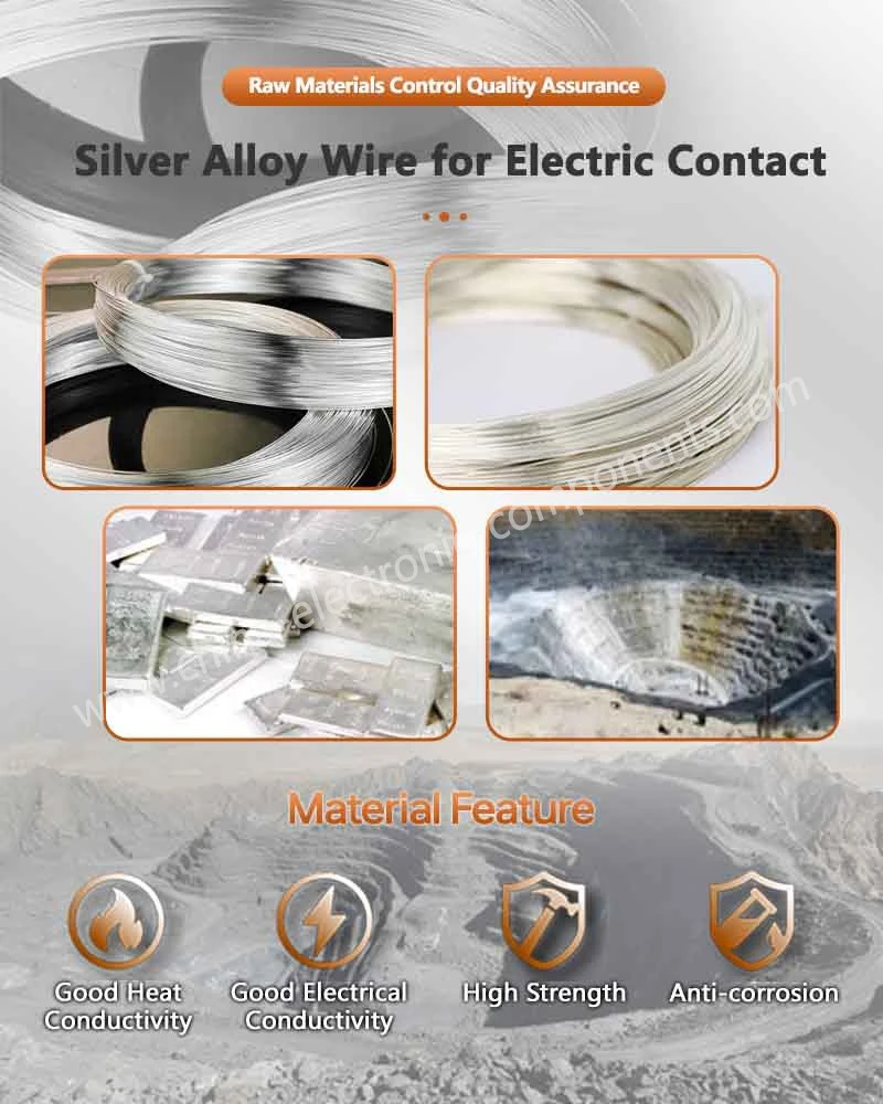
AgFe (Silver-Iron) and AgNi (Silver-Nickel) electrical contact materials have different metallurgical characteristics that influence arc erosion, material transfer, contact resistance, and mechanical wear during DC switching. In low-current inductive circuits, AgFe contacts use a dispersed iron phase within a silver matrix to influence arc-related surface reactions and material transfer, while AgNi contacts rely on a dispersed nickel phase to provide mechanical strength and resistance to contact welding. Xiamen Apollo Electronic Components (Xiamen) Co., Ltd. manufactures silver-based contact materials and silver contact rivets using controlled powder processing, vacuum sintering, and batch density inspection.
DC Inductive Switching: Anode and Cathode Material Transfer Mechanisms
Why DC Switching Causes Directional Contact Erosion
Unlike AC circuits, DC circuits do not have a natural current zero crossing every half-cycle. When contacts separate under inductive load, the stored magnetic energy in the circuit generates an arc that can persist until the gap becomes sufficiently large or the arc is otherwise extinguished.
The polarity of the contacts remains constant during normal DC operation. Consequently, material transfer can develop preferentially between the anode and cathode.
The main erosion mechanisms include:
Pipping: Localized material deposition or protrusion on a contact surface.
Cratering: Localized material loss caused by arc heating and material ejection.
Material transfer: Movement of molten or vaporized contact material from one electrode to another.
Arc erosion: Progressive loss of contact material through repeated electrical discharges.
This energy does not necessarily transfer entirely into the contact arc. The actual arc energy depends on circuit resistance, suppression components, contact separation speed, arc voltage, and the electrical switching arrangement.
Anode and Cathode Erosion Characteristics
During DC interruption, the arc root and thermal loading are influenced by electrode polarity, contact geometry, and the magnetic and electric fields surrounding the contact gap.
| Phenomenon | Anode | Cathode |
| Typical material behavior | Localized melting and erosion | Localized melting and material deposition or erosion |
| Surface morphology | Craters and molten regions | Pips, protrusions, and localized damage |
| Main influencing factors | Arc energy and thermal loading | Electron emission and arc-root behavior |
| Long-term consequence | Contact material loss | Contact geometry variation and unstable contact interface |
The actual erosion pattern depends on the contact alloy, current density, contact force, switching frequency, and circuit suppression strategy. It should be established through polarity-controlled endurance testing rather than assumed from material composition alone.
Why Low-Current Inductive Contacts Require Metallurgical Control
Low-current switching does not automatically mean low contact stress. Inductive loads can produce substantial transient voltage during interruption, while repeated localized arc exposure changes the contact surface.
For weak-current relays and aerospace switching devices, the relevant engineering concerns include:
Contact resistance stability at low operating current.
Surface film formation and oxidation.
Localized arc erosion.
Mechanical contact force retention.
Contact welding and material transfer.
Performance after repeated switching cycles.
A contact material should therefore be selected according to the actual DC voltage, inductance, current, switching frequency, and electrical endurance requirements.
AgFe Fine-Grain Microstructure: Iron Dispersion in a Silver Matrix
Metallurgical Structure of AgFe Electrical Contact Material
AgFe electrical contact material consists of an electrically conductive silver matrix containing a dispersed iron phase.
The silver matrix provides the primary conductive pathway, while the iron phase changes the mechanical and surface behavior of the composite during switching.
The effectiveness of AgFe depends not simply on iron content but also on:
Iron particle size and distribution.
Interparticle spacing.
Silver-to-iron phase continuity.
Composite density and porosity.
Metallurgical bonding between phases.
Consistency between production batches.
A fine and uniform iron dispersion helps reduce localized differences in microstructure. Agglomerated iron particles or excessive porosity can create nonuniform current distribution and localized heating.
Iron Phase and Arc-Related Surface Reactions
Iron has a greater affinity for oxygen than silver under many relevant oxidation conditions. During arc exposure, the dispersed iron phase can participate in surface oxidation reactions, influencing the development of the contact surface.
This mechanism may help modify material transfer and erosion behavior under suitable DC switching conditions.
However, the iron phase does not function as a universal oxygen scavenger. Its effect depends on particle size, exposed surface area, arc temperature, atmosphere, and the formation and removal of oxide products.
The following metallurgical variables should be controlled:
| Microstructural Variable | Potential Impact | Recommended Inspection |
| Iron particle size | Influences dispersion uniformity | Metallographic microscopy |
| Iron distribution | Affects local electrical and thermal behavior | SEM/EDS analysis |
| Composite density | Influences conductivity and mechanical integrity | Density measurement |
| Porosity | Can increase localized heating | Metallographic cross-section |
| Phase bonding | Affects resistance to material loss | Microstructure examination |
| Silver matrix continuity | Maintains conductive pathways | SEM/EDS and conductivity testing |
Fine-Grain Dispersion Versus Particle Agglomeration
A uniform dispersion is preferable to isolated iron-rich clusters because localized phase concentration may create uneven thermal and mechanical behavior.
| Microstructure | Characteristics | Potential Performance Risk |
| Fine, uniform dispersion | Distributed iron particles within the silver matrix | More consistent surface behavior |
| Coarse dispersion | Larger iron-rich regions | Localized differences in erosion |
| Particle agglomeration | Concentrated iron clusters | Uneven current and thermal distribution |
| Excessive porosity | Discontinuous conductive matrix | Increased resistance and local heating |
Request Free Material Evaluation & Quote
AgFe vs. AgNi: Metallurgical and Electrical Performance Comparison
Silver-Iron and Silver-Nickel Material Characteristics
AgFe and AgNi both use silver as the primary conductive matrix, but their dispersed phases differ in mechanical properties, oxidation behavior, and electrical contact performance.
AgNi is commonly selected for general-purpose switching contacts requiring a balance of electrical conductivity, hardness, and resistance to contact welding. AgFe may be evaluated for specific DC switching applications where its iron-containing microstructure offers useful erosion and material-transfer characteristics.
| Characteristic | AgFe | AgNi |
| Base matrix | Silver | Silver |
| Dispersed phase | Iron | Nickel |
| Main metallurgical function | Modifies surface reactions and erosion behavior | Increases hardness and wear resistance |
| Electrical conductivity | Depends on iron fraction and composite density | Depends on nickel fraction and composite density |
| Mechanical characteristics | Influenced by iron dispersion and porosity | Influenced by nickel dispersion and work-hardening behavior |
| DC arc behavior | Requires polarity-specific validation | Requires polarity-specific validation |
| Contact welding resistance | Application-dependent | Commonly used where resistance to welding is required |
| Typical evaluation | Low-current DC switching | General relay and switching applications |
The comparison should not be interpreted as a universal ranking. Contact performance depends on alloy composition, manufacturing route, contact geometry, and the electrical duty cycle.
Electrical Conductivity and Closed-Contact Resistance
The silver matrix provides the primary electrical conduction path. Introducing a second metallic phase generally changes the composite's effective conductivity.
The relationship between material resistivity and conductivity is:
For a contact assembly, however, bulk material conductivity is only one part of total resistance.
A simplified contact resistance model includes:
The interface contribution is influenced by:
Contact force.
Real contact area.
Surface roughness.
Oxide and contamination films.
Contact deformation.
Temperature and switching history.
A material with higher bulk conductivity does not necessarily produce lower assembled contact resistance if its contact geometry or surface condition is poorly controlled.
Mechanical Wear and Contact Stability
Repeated contact closure generates mechanical impact and localized deformation. During long-term operation, this can change the real contact area and contact resistance.
AgFe and AgNi should be evaluated under the same mechanical and electrical conditions when comparing performance.
| Test Parameter | Engineering Objective |
| Contact resistance | Establish initial electrical performance |
| Resistance after endurance | Measure electrical stability |
| Contact force | Evaluate mechanical interface consistency |
| Surface morphology | Identify pitting and cratering |
| Material transfer | Quantify polarity-dependent erosion |
| Contact welding | Evaluate release reliability |
| Mass loss | Measure cumulative contact erosion |
For low-current inductive switching, the material selection should prioritize the actual failure mechanism observed in the relay or switch rather than relying solely on hardness or nominal conductivity.
Vacuum Sintering and Composite Density Control for AgFe Contact Rivets
High-Purity Silver and Iron Powder Preparation
Powder metallurgy is suitable for producing silver-based composite contact materials with controlled phase distribution.
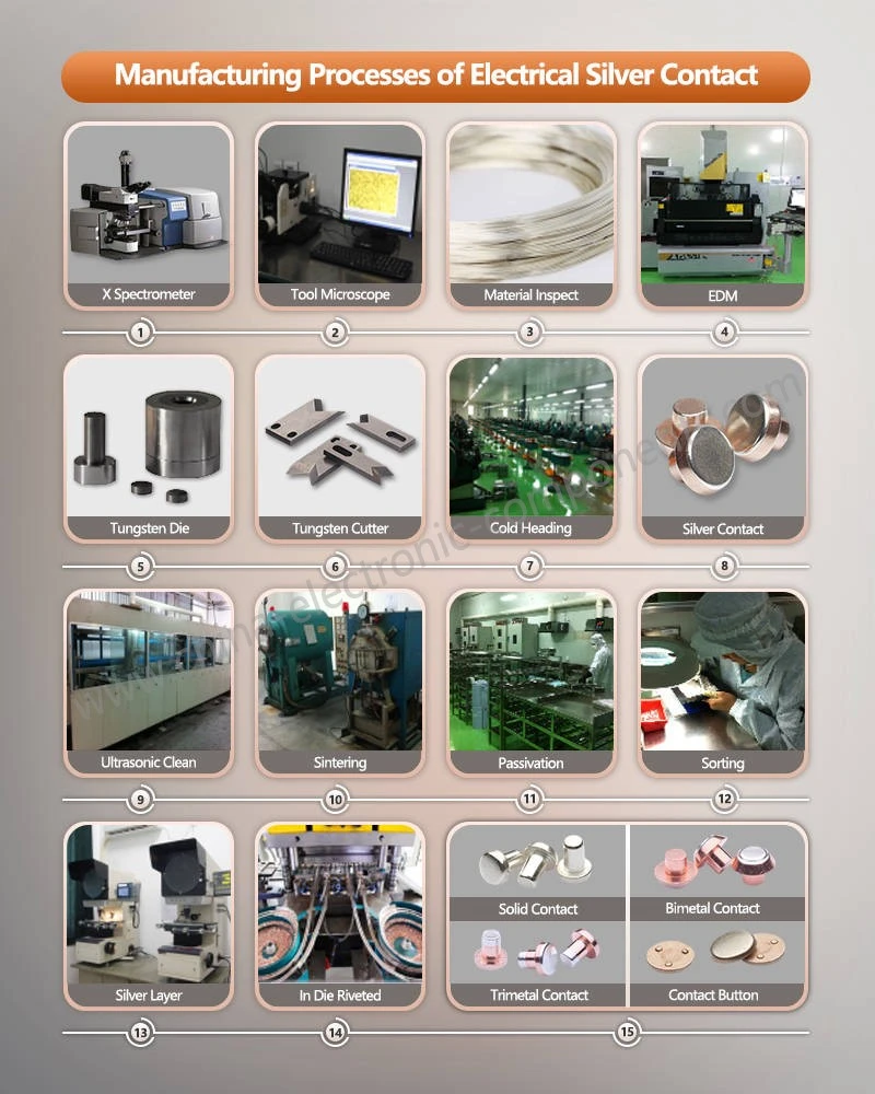
Apollo's AgFe manufacturing process can be structured around high-purity silver powder and iron powder preparation, controlled blending, compaction, vacuum sintering, and subsequent dimensional processing.
The major process stages include:
1. Raw material incoming inspection.
2. Silver and iron powder composition verification.
3. Particle-size distribution assessment.
4. Controlled powder blending.
5. Compaction and green-density control.
6. Vacuum sintering.
7. Density and microstructure inspection.
8. Contact blank machining or forming.
9. Contact rivet production and dimensional verification.
The powder preparation stage is particularly important because uneven blending can result in iron-rich and silver-rich regions in the finished composite.
Vacuum Sintering Parameters and Density Consistency
Vacuum sintering promotes metallurgical bonding between powder particles while limiting contamination from uncontrolled atmospheric exposure.
The process window must be established according to the silver-iron composition, powder characteristics, furnace configuration, and target microstructure.
| Process Variable | Influence on Finished Material | Control Method |
| Powder purity | Affects conductivity and contamination | Incoming material certification |
| Particle-size distribution | Influences packing and dispersion | Particle-size analysis |
| Blending uniformity | Controls phase distribution | Powder sampling and analysis |
| Compaction pressure | Influences green density | Press parameter monitoring |
| Sintering temperature | Controls diffusion and bonding | Calibrated furnace monitoring |
| Vacuum level | Influences atmospheric contamination | Vacuum-record monitoring |
| Sintering time | Affects densification | Validated process recipe |
| Cooling rate | Influences final microstructure | Controlled furnace cooling |
Excessive sintering temperature or inappropriate holding time may cause grain growth or undesirable microstructural changes. Insufficient sintering can leave weak interparticle bonding and residual porosity.
The correct process window must be determined experimentally rather than assigned as a generic temperature range.
Density and Porosity Inspection
Density consistency is a key quality characteristic for silver-based composite contacts.
For a two-phase AgFe composite, theoretical density should account for the actual mass fractions and constituent densities.
Quality verification may include:
Bulk density measurement.
Metallographic porosity analysis.
SEM/EDS elemental distribution.
Electrical resistivity testing.
Hardness measurement.
Dimensional inspection.
Request Free Material Evaluation & Quote
Application Matching: AgFe Contacts for Low-Current DC Relays and Aerospace Switching
Weak-Current Relay Contact Requirements
Weak-current relays operate under conditions where surface contamination and interface resistance can become significant relative to the electrical load.
Typical evaluation factors include:
Low-level contact resistance.
Stable contact force.
Surface oxidation behavior.
Mechanical endurance.
Contact bounce.
Switching reliability after environmental exposure.
AgFe may be considered when the switching duty involves directional DC arc erosion and material-transfer concerns. However, low-level signal switching can also be dominated by surface-film resistance rather than arc erosion.
The selection process must distinguish between two different operating conditions:
Low-level signal switching: Contact resistance, surface cleanliness, and film behavior dominate.
Inductive DC switching: Arc erosion, material transfer, contact welding, and interruption characteristics become more significant.
AgFe is not automatically the preferred material for both conditions.
Aerospace Electrical Switches: Environmental and Reliability Requirements
Aerospace switching components may operate under temperature variation, vibration, mechanical shock, and strict reliability requirements.
For these applications, the contact material must be evaluated together with the complete switching assembly.
| Application Condition | Main Risk | Required Validation |
| Low-current DC switching | Interface resistance instability | Low-level resistance testing |
| Inductive DC interruption | Directional arc erosion | Polarity-specific endurance testing |
| High switching frequency | Accelerated mechanical and electrical wear | Endurance testing |
| Temperature variation | Resistance and force variation | Temperature-cycle testing |
| Vibration exposure | Intermittent contact | Vibration and continuity monitoring |
| Long service life | Contact degradation | Accelerated life testing |
Applicable aerospace or industrial qualification standards should be selected according to the end-product specification. Material-level testing alone cannot establish compliance of the complete relay or switch.
AgFe vs. AgNi Selection Matrix
| Selection Requirement | AgFe Evaluation | AgNi Evaluation |
| Directional DC arc erosion | Assess iron-phase influence on material transfer | Compare erosion under identical polarity |
| Low-level contact resistance | Verify surface-film and interface stability | Verify surface-film and interface stability |
| Mechanical wear | Measure hardness and endurance behavior | Evaluate hardness and wear resistance |
| Contact welding | Conduct application-specific switching tests | Conduct application-specific switching tests |
| Composite consistency | Verify iron dispersion and density | Verify nickel dispersion and density |
| Production suitability | Assess powder metallurgy capability | Assess established material and joining route |
The final material should be selected using comparative test data from the actual relay design, including contact force, circuit inductance, rated current, interruption voltage, and endurance-cycle requirements.
Quality Assurance and Batch Traceability for AgFe Electrical Contact Materials
Critical-to-Quality Characteristics for Silver-Iron Contacts
For procurement and engineering qualification, the following characteristics should be defined before production release.
| CTQ Characteristic | Inspection Method | Quality Objective |
| Silver-iron composition | Chemical composition analysis | Confirm approved material formulation |
| Iron particle distribution | Metallographic microscopy / SEM-EDS | Verify dispersion uniformity |
| Composite density | Density measurement | Control batch consistency |
| Porosity | Metallographic analysis | Prevent excessive internal voids |
| Electrical resistivity | Electrical testing | Verify conductive performance |
| Hardness | Microhardness testing | Confirm mechanical properties |
| Contact dimensions | Optical measurement / CMM | Meet approved drawing |
| Contact resistance | Four-wire measurement | Verify electrical interface |
| Switching endurance | Relay-level endurance testing | Evaluate actual service performance |
Production Documentation and Customer Qualification
For automotive and industrial relay programs, qualification documentation may include:
Material certificates.
Process flow diagrams.
PFMEA.
Control plans.
Dimensional inspection reports.
Metallographic analysis reports.
Electrical performance test reports.
PPAP Level 3 documentation, where required.
Apollo's manufacturing and inspection processes should connect material batch identification with powder preparation, sintering records, downstream processing, and final contact inspection.
This traceability structure allows engineering teams to investigate changes in contact resistance, erosion patterns, or material density across production lots.
Frequently Asked Questions
1. What is the main difference between AgFe and AgNi electrical contact materials for DC switching?
AgFe contains dispersed iron within a silver matrix and may influence arc-related surface reactions and directional material transfer. AgNi uses dispersed nickel to improve mechanical strength and wear behavior. Final selection requires application-specific endurance testing.
2. How does vacuum sintering improve AgFe silver contact rivet consistency?
Vacuum sintering promotes bonding between silver and iron powder particles while controlling atmospheric contamination. Powder blending, compaction density, furnace conditions, and porosity inspection determine final batch consistency.
3. How can buyers verify the quality of AgFe electrical contact materials?
Request composition analysis, density reports, metallographic images, SEM/EDS phase-distribution results, hardness data, electrical resistivity measurements, and application-specific DC switching endurance reports.
contact us
Send Inquiry