



Ultrasonic Metal Welding vs. Laser Welding for Multi-Layer Flexible Copper and Aluminum Foils
Nov 16, 2026
Leave a message
Joining 50–100 layers of copper or aluminum foil, with individual foil thicknesses of 0.05–0.2 mm, requires controlled energy input, uniform interfacial bonding, and low electrical contact resistance. Ultrasonic metal welding uses high-frequency mechanical vibration and pressure to create a solid-state metallurgical bond without bulk melting, making it suitable for multi-layer flexible busbar connections where thermal distortion and brittle intermetallic formation must be controlled. Fiber laser welding offers higher localized energy density but requires tighter control of penetration, heat input, and material compatibility.
For EV battery connections, energy storage systems (ESS), and high-current electrical assemblies, the selection between ultrasonic welding and laser welding should be based on layer count, material combination, joint geometry, electrical resistance, mechanical strength, and production repeatability.
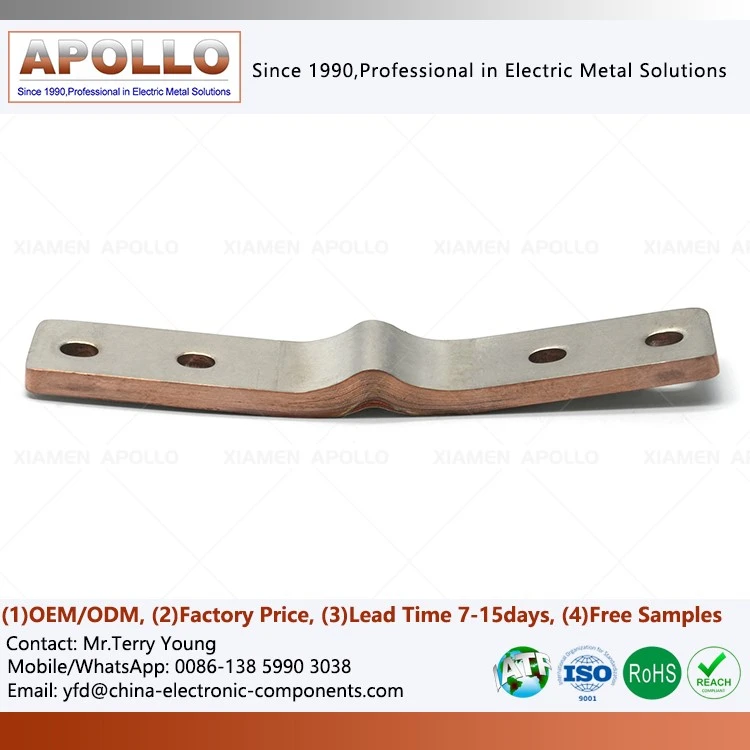
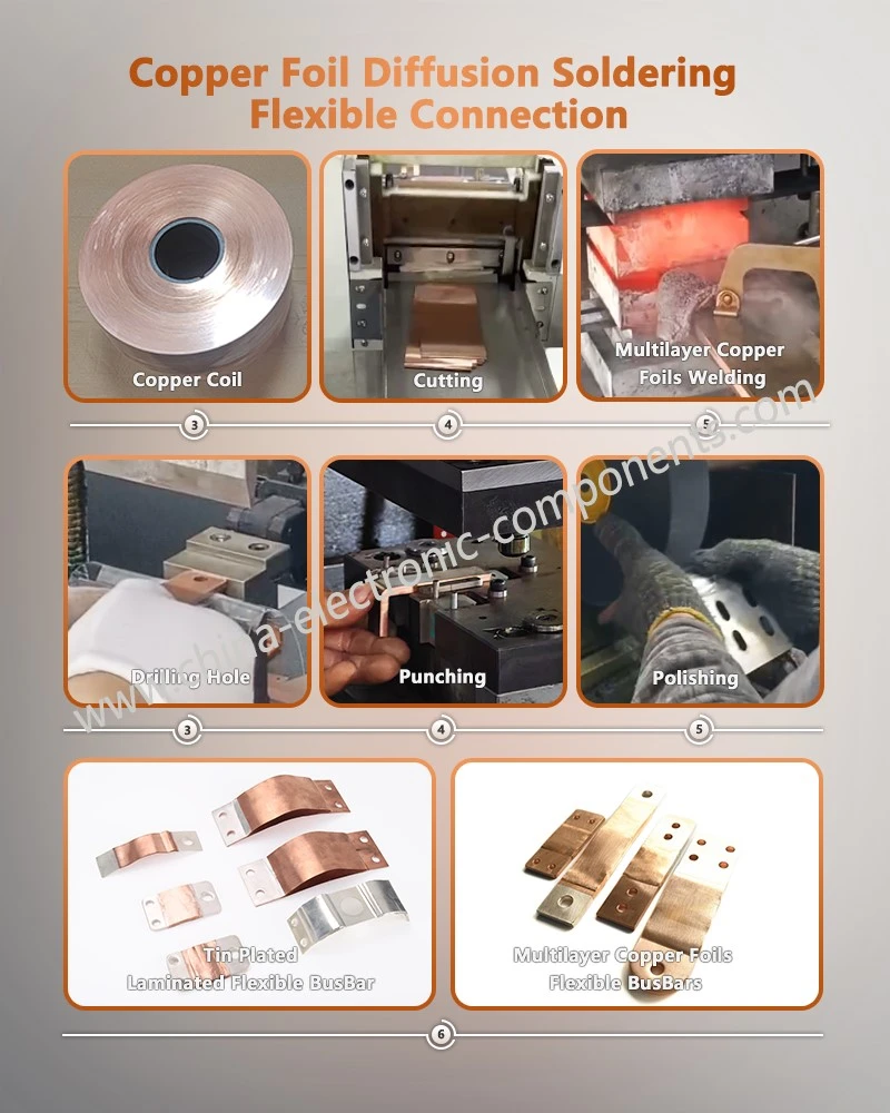
Xiamen Apollo Electronic Components (Xiamen) Co., Ltd. manufactures flexible copper foil connectors and laminated metal connection components, with automated ultrasonic welding processes for multi-layer foil assemblies.
Engineering Challenges of Welding 50–100 Layers of 0.05–0.2 mm Copper and Aluminum Foils
Multi-Layer Foil Stacking and Interfacial Bonding Requirements
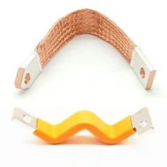
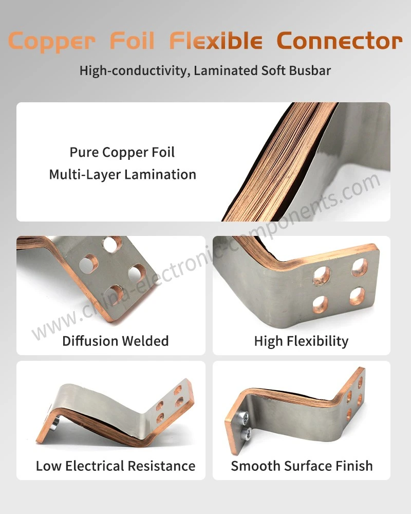
Flexible copper foil busbars typically consist of multiple thin conductive sheets joined at their terminal sections while retaining flexibility in the unbonded region.
A typical assembly may contain:
| Parameter | Typical Design Range | Engineering Consideration |
| Individual foil thickness | 0.05–0.20 mm | Influences deformation and energy transfer |
| Foil layer count | 50–100 layers | Determines total stack thickness |
| Copper material | C1100 / C1020 | Electrical conductivity and ductility |
| Aluminum material | 1050 / 1060 / 3003 | Conductivity and forming characteristics |
| Joint configuration | Multi-layer terminal bonding | Requires uniform interfacial contact |
| Application | EV / ESS/inverter connections | Electrical and mechanical durability |
For reference, a stack of 50 layers of 0.1 mm foil has a nominal material thickness of 5 mm before compression. A 100-layer stack of the same foil thickness reaches 10 mm.
This creates several manufacturing difficulties:
Uneven pressure distribution across the foil stack.
Insufficient bonding between internal foil interfaces.
Localized deformation near the welding boundary.
Foil wrinkling and edge displacement.
Excessive welding energy causing surface damage.
Inconsistent electrical resistance between production batches.
The welding process must establish bonding throughout the intended joint area rather than producing a strong bond only at the outermost layers.
Copper and Aluminum Material Compatibility
Copper and aluminum have different electrical, thermal, and mechanical properties. Their combination introduces additional challenges during joining.
| Material Property | C1100 Copper | 1060 Aluminum |
| Electrical conductivity | Approximately 100% IACS | Approximately 61% IACS |
| Density | Approximately 8.96 g/cm³ | Approximately 2.70 g/cm³ |
| Thermal conductivity | Approximately 390 W/(m·K) | Approximately 230 W/(m·K) |
| Melting temperature | Approximately 1083°C | Approximately 660°C |
| Oxide behavior | Relatively stable surface oxide | Strong, persistent Al₂O₃ film |
Values are approximate reference figures; actual properties depend on material grade, temper, and product condition.
Copper-aluminum welding requires particular attention to the formation of Cu-Al intermetallic compounds. Excessive thermal input during fusion welding can generate brittle intermetallic layers that reduce joint ductility and fatigue resistance.
Ultrasonic solid-state welding reduces this risk by avoiding bulk melting, although localized interfacial heating and reaction products may still occur depending on the process conditions.
Ultrasonic Metal Welding Mechanism: Solid-State Bonding Without Bulk Melting
High-Frequency Mechanical Vibration and Interfacial Bond Formation
Ultrasonic metal welding generally combines three inputs:
1. Normal clamping force.
2. High-frequency mechanical vibration.
3. Controlled vibration amplitude and welding duration.
The sonotrode applies mechanical oscillation to the foil stack while the fixture or anvil supports the opposite side.
The relative movement generates interfacial friction and plastic deformation. Surface oxides and contaminants are disrupted, allowing clean metal surfaces to establish intimate contact.
As deformation progresses, metallic bonding develops across the contact interfaces through localized plastic flow and atomic-scale interaction.
The process is classified as solid-state welding because the joint is formed without requiring the bulk metal to melt.
Typical industrial ultrasonic metal welding systems operate within the following general equipment ranges:
| Process Variable | Common Equipment Range | Effect on Weld Quality |
| Welding frequency | 20–40 kHz | Determines vibration frequency |
| Vibration amplitude | Approximately 10–50 μm | Influences interfacial deformation |
| Welding pressure | Machine- and geometry-dependent | Controls contact and consolidation |
| Welding duration | Application-dependent | Determines energy transfer |
| Weld energy | Recipe-dependent | Influences bond formation |
| Hold time | Application-dependent | Stabilizes the joint after vibration |
These are equipment-level reference ranges, not universal process settings for 50–100-layer assemblies. Actual parameters must be established through DOE trials and destructive joint validation.
Why Solid-State Welding Reduces Thermal Damage
Unlike fusion welding, ultrasonic welding does not require the entire joint interface to reach the melting temperature.
This offers several engineering advantages:
Reduced bulk thermal distortion.
Lower risk of fusion-related porosity.
Reduced formation of thick Cu-Al intermetallic layers.
No conventional laser-induced molten-metal spatter.
Lower thermal impact on nearby insulation and flexible foil sections.
However, ultrasonic welding is not a zero-temperature process. Localized frictional heating occurs during bonding, and excessive energy can cause foil tearing, surface indentation, or localized metallurgical changes.
The process window must therefore balance interfacial bonding strength against material damage.
Ultrasonic Welding Process Window for 50–100 Foil Layers
For high-layer-count assemblies, the process window becomes narrower because mechanical vibration must be transmitted through a thicker stack.
Excessive clamping force may cause foil extrusion or edge deformation. Insufficient force may prevent effective interfacial contact.
A controlled process-development matrix should include:
| Variable | Too Low | Too High |
| Welding amplitude | Incomplete interfacial bonding | Foil tearing and surface damage |
| Clamping force | Poor contact and slipping | Excessive compression |
| Welding duration | Insufficient bonding | Overwelding and fatigue damage |
| Energy input | High contact resistance | Excessive deformation |
| Fixture stiffness | Unstable energy transfer | Excessive local constraint |
For multi-layer copper foil bonding OEM projects, welding energy and displacement monitoring should be evaluated together. A single fixed welding time does not adequately describe the bonding condition across different foil thicknesses and layer counts.
Request Free DFM Evaluation & Quote
Ultrasonic Metal Welding vs. Fiber Laser Welding: Process and Performance Comparison
Heat Input, Spatter, and Metallurgical Characteristics
Ultrasonic welding and fiber laser welding use different physical mechanisms.
Ultrasonic welding relies on mechanical vibration and pressure, while laser welding relies on concentrated optical energy to generate localized melting and fusion.
The distinction is particularly important when joining thin copper and aluminum foils.
| Comparison Parameter | Ultrasonic Metal Welding | Fiber Laser Welding |
| Joining mechanism | Solid-state bonding | Fusion welding |
| Bulk melting | Not required | Required |
| Heat-affected zone | No conventional fusion HAZ; localized heating occurs | Present around the fusion zone |
| Spatter | No conventional molten-metal spatter; particles may still occur | Possible, depending on process stability |
| Cu-Al intermetallic risk | Generally lower due to solid-state joining | Higher risk with excessive thermal input |
| Foil deformation | Controlled by pressure and vibration | Controlled by heat input and fixture design |
| Surface preparation | Oxide and contamination control required | Surface condition and reflectivity affect absorption |
| Joint geometry | Requires suitable tool access and clamping | Requires optical access and weld-path clearance |
| Tool wear | Sonotrode and anvil wear | No contact welding tool |
| Typical application | Multi-layer flexible foil terminals | Localized fusion joints and selected terminal geometries |
The absence of a conventional fusion zone is a major advantage of ultrasonic welding for applications where brittle intermetallic formation must be limited.
Laser welding remains suitable for geometries where non-contact joining, narrow weld paths, and localized fusion are required.
Tool Wear and Long-Run Production Stability
Ultrasonic welding requires direct contact between the sonotrode, workpiece, and supporting fixture.
The sonotrode surface gradually wears during production. Changes in surface texture and geometry can influence vibration transmission and bonding consistency.
| Production Factor | Ultrasonic Welding | Fiber Laser Welding |
| Main equipment wear | Sonotrode and anvil | Optical and motion-system components |
| Consumable tooling | Contact welding tools | No direct-contact welding tool |
| Maintenance focus | Tool-face condition and alignment | Optics, focus, and protective glass |
| Process drift | Tool wear and fixture condition | Focus shift and optical contamination |
| In-process monitoring | Energy, amplitude, force, displacement | Power, speed, focus, and weld monitoring |
For automated ultrasonic metal welding busbar production, tool-life monitoring should be based on actual weld-quality trends rather than a fixed replacement interval alone.
Application Selection Matrix for EV and ESS Flexible Connectors
| Application Requirement | Preferred Process | Engineering Reason |
| 50–100 layers of thin copper foil | Ultrasonic welding | Solid-state bonding of stacked foils |
| Thin copper-aluminum foil combination | Ultrasonic welding, subject to validation | Lower bulk thermal input |
| Narrow localized fusion seam | Fiber laser welding | Precise non-contact energy delivery |
| High-density foil terminal consolidation | Ultrasonic welding | Mechanical consolidation of multiple layers |
| Complex three-dimensional weld path | Fiber laser welding | Flexible beam positioning |
| Reduced fusion-related intermetallic formation | Ultrasonic welding | No bulk melting |
| Minimal mechanical deformation requirement | Fiber laser welding may be suitable | No sonotrode clamping at the weld interface |
The final selection must be validated against peel strength, electrical resistance, thermal cycling, and mechanical fatigue requirements.
Request Free DFM Evaluation & Quote
Weld Quality Inspection: Metallographic Analysis, Peel Testing, and Millivolt Voltage Drop
Metallographic Cross-Section Analysis of Multi-Layer Welds
Metallographic inspection provides direct evidence of the internal bonding condition.
For multi-layer foil welding, the cross-section should be prepared perpendicular to the weld direction and evaluated under an optical microscope or metallographic imaging system.
Inspection should focus on:
Bonded interface continuity.
Unbonded regions between foil layers.
Excessive plastic deformation.
Localized cracking.
Foil thinning and extrusion.
Cu-Al interfacial reaction layers where applicable.
For copper-aluminum joints, SEM and EDS analysis can provide additional information about interfacial morphology and elemental distribution.
A single cross-section cannot represent the entire weld. Multiple sampling positions should be selected according to weld length, geometry, and the customer's validation plan.
Peel Strength and Pull-Out Force Testing
Mechanical testing evaluates whether the welded terminal can withstand assembly loads, vibration, and repeated mechanical stress.
Two common approaches are:
Peel testing
Evaluates the resistance of bonded foil layers to separation.
Helps identify insufficient interfacial bonding.
Provides comparative data for process optimization.
Pull-out or tensile testing
Evaluates the maximum load sustained by the welded terminal.
Identifies the failure location and failure mode.
Supports comparison between production batches.
For 50–100-layer assemblies, the test method must define specimen geometry, gripping arrangement, loading speed, and failure criteria.
| Test Characteristic | Measurement | Quality Objective |
| Maximum peel force | N or N/mm | Evaluate interfacial bonding |
| Maximum tensile load | N | Verify terminal mechanical strength |
| Failure mode | Interface/foil tearing/base-metal failure | Identify bonding mechanism |
| Weld deformation | mm | Evaluate dimensional stability |
| Test repeatability | Statistical distribution | Monitor production consistency |
A high pull force alone does not prove that every internal foil interface is bonded. Mechanical testing should be combined with cross-sectional inspection.
Recommended Quality Control Matrix for Production Release
| Inspection Stage | Inspection Method | Frequency |
| Incoming material | Thickness, grade, surface condition | Each material lot |
| Foil stacking | Layer count and alignment | Each production batch |
| Welding setup | Parameter and tool verification | Start-up and changeover |
| In-process welding | Energy, force, displacement monitoring | According to the control plan |
| Weld geometry | Visual and dimensional inspection | Defined sampling plan |
| Mechanical validation | Peel or pull testing | Defined sampling plan |
| Electrical validation | Four-wire resistance measurement | Defined sampling plan |
| Process qualification | Metallographic cross-section | Initial qualification and periodic review |
Acceptance values should be established through customer drawings, application requirements, and process validation. ISO 9001 or IATF 16949 quality-system certification does not replace product-specific weld qualification.
Apollo Automated Ultrasonic Welding Workstation for Flexible Copper Foil Connectors
Automated Foil Stacking and Positioning
Stable multi-layer foil welding begins before the welding cycle.
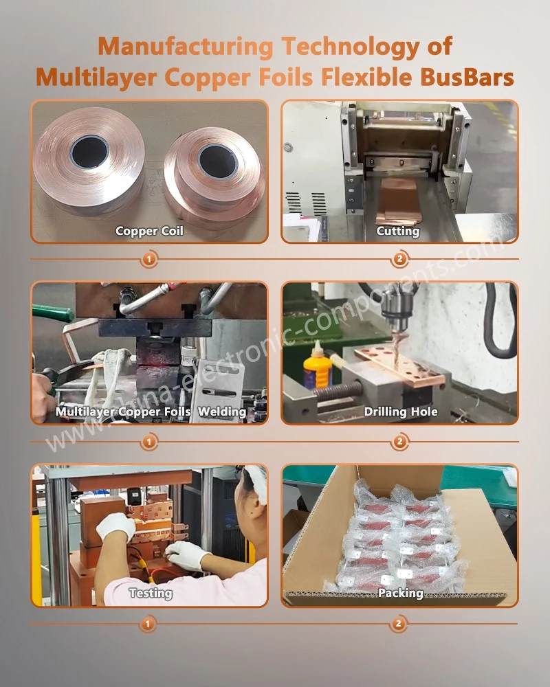
Apollo's production engineering approach integrates the following process stages:
1. Copper or aluminum foil material preparation.
2. Precision cutting and blanking.
3. Layer counting and stacking.
4. Positioning and fixture clamping.
5. Ultrasonic welding.
6. Weld appearance and dimensional inspection.
7. Electrical and mechanical quality verification.
For 50–100-layer products, stacking accuracy is particularly important. Misaligned layers may produce uneven pressure distribution and incomplete bonding at the weld boundary.
The fixture must provide adequate support while allowing consistent energy transfer through the intended bonding region.
Ultrasonic Welding Process Monitoring
Automated ultrasonic welding equipment can record key process parameters for each weld cycle.
| Monitoring Parameter | Function |
| Welding energy | Tracks energy delivered during bonding |
| Welding time | Monitors cycle duration |
| Vibration amplitude | Controls mechanical oscillation |
| Clamping force | Maintains interface pressure |
| Displacement | Tracks stack compression |
| Tool condition | Identifies progressive sonotrode wear |
Combining these parameters provides a basis for process traceability and abnormal-cycle detection.
A parameter record alone does not establish weld integrity. Correlation with destructive testing and electrical resistance measurements is required to establish the process acceptance window.
Production Consistency for EV Battery and ESS Applications
Flexible copper foil connectors are used where rigid busbars cannot adequately accommodate vibration, thermal movement, or assembly displacement.
Typical applications include:
EV battery module interconnections.
Battery pack positive and negative terminals.
ESS battery cluster connections.
Inverter and power distribution connections.
High-current flexible links between electrical components.
Apollo's manufacturing scope includes flexible copper foil connectors and associated precision metal components. Production qualification should establish the permitted foil count, material combination, terminal geometry, resistance range, and mechanical strength for each customer program.
OEM Selection Criteria for a Multi-Layer Foil Welding Supplier
Selecting a multi-layer foil welding supplier requires evaluation of both process capability and electrical performance.
A suitable supplier should demonstrate the ability to control the complete manufacturing sequence rather than relying exclusively on welding equipment specifications.
| Supplier Evaluation Item | Required Evidence |
| Material capability | C1100, C1020, 1050, 1060, or approved grades |
| Foil thickness | Verified capability for 0.05–0.20 mm foils |
| Layer-count capability | Validated production range up to 50–100 layers |
| Welding process | Documented ultrasonic welding parameters |
| Mechanical testing | Peel and tensile test reports |
| Electrical testing | Four-wire micro-resistance measurement |
| Metallographic inspection | Weld cross-section analysis |
| Tooling management | Sonotrode condition and replacement records |
| Quality management | Applicable ISO 9001 / IATF 16949 documentation |
| Production traceability | Batch identification and process records |
For OEM development, the initial engineering review should include the 2D drawing, 3D model, material specifications, foil layer count, rated current, operating temperature, and mechanical loading conditions.
The supplier can then establish the welding fixture, process window, inspection plan, and prototype validation schedule.
Frequently Asked Questions
1. Can ultrasonic metal welding join 50–100 layers of 0.05 mm copper foil?
Yes, provided the ultrasonic equipment, sonotrode geometry, fixture stiffness, and welding parameters are validated for the stack configuration. Cross-sectional analysis, peel testing, and four-wire resistance measurement should confirm internal bonding quality.
2. Is ultrasonic welding better than laser welding for copper-aluminum flexible busbars?
Ultrasonic welding is generally preferable when joining multiple thin foil layers because it avoids bulk melting and reduces fusion-related intermetallic formation. Laser welding is suitable for localized fusion joints requiring non-contact processing.
3. How does a multi-layer foil welding supplier verify low electrical contact resistance?
The supplier uses four-wire Kelvin measurement under a defined test current and temperature. Voltage drop is converted into joint resistance using Ohm's law, with acceptance limits established by the customer's electrical design specification.
contact us
Send Inquiry