




In-Die Tapping and Fastener Staking in Relay Yoke Stamping: Eliminating Secondary Assembly Operations
Nov 02, 2026
Leave a message
In-die tapping and fastener staking integrate thread production and mechanical fastening directly into a progressive stamping line, reducing separate machining, manual handling and secondary assembly operations. For precision relay yokes made from cold-rolled electrical steel, servo-synchronized roll forming taps can produce chip-free internal threads, while controlled staking secures fasteners within the same die sequence. The resulting process reduces work-in-process transfers and creates a more controlled route for thread geometry, fastener position and assembly repeatability.
Why Secondary Tapping Creates Quality Risks in Relay Yoke Stamping
Relay yokes are magnetic circuit components used in electromagnetic relays and high-voltage contactors. Their geometry influences magnetic flux paths, armature alignment and the mechanical positioning of the assembled relay structure. Threaded holes and fixed fasteners may also provide mounting points for coils, brackets, terminals or other structural components.
When tapping is performed after stamping, the component must pass through an additional machining and handling stage. This separation introduces process variables that are difficult to control through stamping inspection alone.
Thread defects caused by offline tapping
Manual or independently operated tapping processes can introduce several recurring defects:
Incomplete threads: Incorrect tapping depth, tool wear or workpiece positioning can leave insufficient effective thread engagement.
Cross-threading: Misalignment between the tap and pre-punched hole can damage the first thread turns.
Burr contamination: Cutting taps generate metal chips and burrs that may remain inside threaded holes or on the yoke surface.
Thread-size variation: Tool wear, spindle runout and inconsistent feed rates can affect pitch diameter and thread profile.
Material mix-ups: Separate machining batches increase the risk of combining components with different thread specifications or production revisions.
Handling damage: Repeated transfers between stamping, tapping, cleaning and assembly can cause scratches, deformation and edge damage.
These defects have direct consequences for downstream assembly. A damaged thread may prevent a fastener from reaching the specified seating position. Excessive burrs can interfere with component contact, while inconsistent thread geometry can produce unstable installation torque.
Quality risks across separate production stages
| Offline operation | Typical process risk | Potential effect on relay assembly | Recommended control |
| Hole punching | Hole diameter variation, burr formation | Incorrect thread-forming conditions | Punch-to-tap dimensional verification |
| Manual or machine tapping | Misalignment, incomplete thread | Reduced engagement or assembly failure | Thread gauge and tapping-depth inspection |
| Part transfer | Scratches, deformation, mixed batches | Positioning and dimensional inconsistency | Batch identification and protective handling |
| Chip cleaning | Residual metal particles | Contamination of relay components | Cleaning validation and visual inspection |
| Fastener installation | Inconsistent insertion depth | Loose or misaligned fastening | Insertion-force and position monitoring |
The core process issue is not simply the number of operations. It is the loss of direct process control when hole formation, thread production and fastening are distributed across separate production stations.
For relay yokes with closely controlled mounting positions, combining these operations within a progressive die can reduce the number of independent handling and alignment steps.
Servo-Synchronized Roll Forming Taps for Chip-Free Internal Threads
Unlike conventional cutting taps, roll forming taps create internal threads by plastically displacing material rather than removing it. The process is also known as thread forming or chipless tapping.
For suitable ductile steel grades and thread geometries, this method can be integrated into a progressive stamping die to produce internal threads during the indexed press cycle.
Roll forming versus conventional cutting taps
| Engineering factor | Cutting tap | Roll forming tap |
| Material removal | Removes material to generate the thread | Displaces material through plastic deformation |
| Metal chips | Generates chips | Chip-free under normal forming conditions |
| Thread profile | Produced by cutting edges | Produced by material displacement |
| Surface condition | Depends on cutting quality and tool condition | Can provide a work-hardened thread surface |
| Material suitability | Broad range of machinable materials | Requires sufficient ductility and suitable forming properties |
| Lubrication | Generally required | Forming lubrication is generally required |
| Main failure risks | Tool breakage, chip packing, incomplete cutting | Excessive forming torque, material cracking, dimensional instability |
Roll forming is not automatically suitable for every relay yoke. Material grade, hardness, sheet thickness, pre-hole diameter, thread pitch and available forming depth must be evaluated together.
Material flow and thread formation in cold-rolled electrical steel
Cold-rolled electrical steel is commonly selected for relay magnetic circuit components because of its magnetic properties and dimensional availability. However, its forming response varies with grade, thickness, temper and mechanical properties.
During thread forming, the tap lobes apply radial pressure to the pre-punched hole wall. Material flows into the thread profile, creating the required internal geometry without conventional chip removal.
The process depends on several interacting variables:
1. Pre-hole diameter: A hole that is too small increases forming torque and may cause cracking or tool overload. A hole that is too large can result in insufficient thread height.
2. Material hardness: Higher hardness generally increases forming resistance and may reduce the process window.
3. Sheet thickness: Available engagement length determines the effective number of load-bearing thread turns.
4. Tap geometry: Lobe geometry, lead angle and coating influence forming load and tool wear.
5. Lubrication: Lubricant selection and delivery affect friction, heat generation and tool service life.
6. Servo synchronization: Tap rotation and axial movement must match the press position and forming depth.
The pre-hole diameter should be established through material-specific trials rather than copied directly from a cutting-tap chart. A forming tap requires a different starting-hole specification because the final thread is generated through material displacement.
Servo synchronization and progressive die integration
In a progressive die, each press stroke advances the strip through a sequence of stations. In-die tapping introduces a rotating tool operation that must be synchronized with strip indexing and press motion.
A servo-controlled tapping unit can coordinate:
Tap rotation speed.
Axial feed and withdrawal.
Thread-forming depth.
Tool position relative to the punched hole.
Cycle timing with the press stroke.
Tool overload detection and fault response.
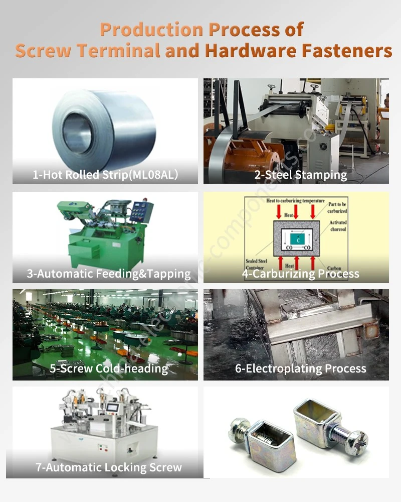
A practical sequence may include pilot positioning, hole punching, thread forming and subsequent fastener staking. The exact station arrangement depends on the yoke geometry, strip layout, press architecture and tool access.
Process variables and failure prevention
| Process variable | Typical defect if uncontrolled | Engineering control |
| Pre-hole diameter | Low thread height or excessive forming torque | Establish material-specific hole limits |
| Tap runout | Uneven thread profile | Check tool-holder concentricity |
| Axial feed | Incomplete or over-formed threads | Synchronize feed with tap pitch |
| Forming depth | Insufficient engagement or bottoming | Set and verify depth limits |
| Lubricant delivery | Excessive friction and tool wear | Monitor lubricant condition and supply |
| Tap wear | Thread geometry drift | Define tool-life criteria using inspection data |
| Strip positioning | Thread-to-datum position error | Control pilot and feed accuracy |
Request In-Die Tapping DFM Evaluation
Thread Strength: Material Flow, Pull-Out Load and Stripping Torque
The mechanical performance of a formed thread depends on more than nominal thread dimensions. Material properties, engagement length, thread geometry and installation conditions all influence pull-out resistance and stripping torque.
One important characteristic of roll-formed threads is that the original material is displaced rather than cut away. Under suitable forming conditions, the material flow around the thread profile remains continuous, and local plastic deformation can increase surface hardness.
However, improved thread strength must be demonstrated through component testing. It should not be assumed solely from the forming method.
Why material flow affects thread performance
In a cutting-tapped hole, the thread profile is produced by removing material from the hole wall. The resulting thread geometry depends on the cutting operation and the remaining material section.
In a roll-formed thread, the tap lobes displace material into the thread valleys. This can produce:
Continuous material flow around the formed profile.
Local work hardening near the thread surface.
Reduced chip-related contamination.
A thread profile with a different surface condition from a cut thread.
For relay yokes, the practical benefit is a potential improvement in resistance to thread stripping and fastener pull-out when the material and forming conditions are correctly matched.
Pull-out force and stripping torque are different measurements
These two tests evaluate different failure mechanisms and should not be treated as interchangeable.
| Test | What it measures | Main failure mode | Relevant process variables |
| Thread pull-out test | Axial force required to extract a threaded fastener | Thread shear or material failure | Engagement length, sheet thickness, material strength |
| Thread stripping torque test | Torque at which the internal or external thread fails | Thread flank deformation or stripping | Thread profile, material hardness, fastener grade |
| Installation torque test | Torque required to install the fastener | Friction and seating resistance | Surface finish, lubrication, fastener coating |
| Loosening resistance test | Resistance to fastener rotation under specified loading | Loss of clamp force or rotational loosening | Joint design, preload, vibration conditions |
For thin-sheet relay yokes, the available thread engagement length may be the limiting factor. Increasing the thread-forming quality cannot compensate indefinitely for insufficient material thickness.
Where higher axial loads are required, engineering options may include:
Increasing local sheet thickness.
Adding an extruded or formed boss where geometry permits.
Using a self-clinching or staking fastener.
Introducing a threaded insert.
Revising the fastener diameter or engagement design.
The selected solution must account for magnetic circuit requirements, available package space and the assembly load path.
Establishing a measurable thread-strength validation plan
A useful validation plan should connect the thread specification to the actual assembly function.
| Validation item | Inspection method | Acceptance basis |
| Internal thread size | GO/NO-GO thread gauge | Approved drawing and thread standard |
| Effective thread depth | Depth gauge or section measurement | Drawing-defined engagement |
| Thread profile | Optical measurement or metallographic section | Approved thread geometry |
| Pull-out resistance | Axial tensile test | Customer-defined minimum load |
| Stripping torque | Calibrated torque test | Customer-defined minimum torque |
| Installation torque | Torque-controlled assembly test | Approved assembly specification |
| Repeatability | Statistical sampling across production batches | Control plan and customer requirements |
Do not use a universal pull-out force or stripping torque for all relay yokes. The required values depend on thread size, material grade, sheet thickness, fastener specification and assembly design.
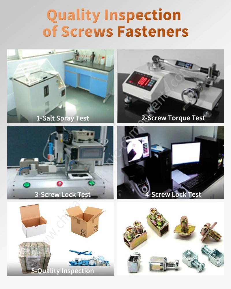
In-Die Fastener Staking: Automated Insertion and Mechanical Retention
In-die fastener staking integrates the insertion and mechanical locking of fasteners into the progressive stamping sequence. It is suitable for relay yokes that require fixed studs, threaded inserts, locating pins or other fastening elements.
The process uses controlled deformation of the surrounding sheet metal or fastener feature to create mechanical retention. Unlike adhesive bonding, staking relies on the geometry and plastic deformation of the joined components.
Fastener insertion and staking sequence
A typical automated sequence includes:
1. Fastener feeding: A dedicated feeding system supplies the specified fastener in a controlled orientation.
2. Positioning: The fastener is aligned with the receiving hole or formed feature in the relay yoke.
3. Insertion: The fastener enters the prepared opening under controlled force and displacement.
4. Staking: A punch or forming tool deforms the designated material to lock the fastener.
5. Position verification: Insertion height, protrusion and position are checked against the drawing.
6. Process monitoring: Abnormal feeding, missing fasteners or incomplete staking trigger the defined fault response.
The insertion and staking stations must be designed around the fastener geometry, sheet thickness, material hardness and required retention force.
Fastener retention methods and process selection
| Joining method | Retention principle | Suitable application | Main engineering consideration |
| Clinching | Local sheet-metal deformation mechanically locks components | Thin-sheet assemblies | Joint geometry and remaining sheet thickness |
| Staking | Controlled plastic deformation secures a fastener | Fixed pins, studs and inserts | Staking height and deformation consistency |
| Press-fit insertion | Interference between fastener and hole provides retention | Precision pins and selected inserts | Hole tolerance and insertion force |
| In-die riveting | Rivet deformation creates a permanent mechanical joint | Multi-layer sheet-metal assemblies | Rivet geometry and joint stack-up |
| Thread forming | Material displacement produces internal threads | Direct threaded mounting features | Ductility, engagement length and forming load |
Staking is not a substitute for thread forming in every design. A relay yoke may require both operations: an internal thread for screw fastening and a staked fastener for a permanent mechanical connection.
Critical dimensions for automated fastener insertion
| CTQ characteristic | Why it matters | Recommended control |
| Receiving-hole diameter | Determines insertion interference | Hole-size inspection |
| Fastener concentricity | Controls alignment with mating components | Datum-based dimensional inspection |
| Insertion height | Affects assembly stack-up | Height gauge or optical measurement |
| Staking diameter | Influences mechanical retention | Tooling dimension and sample inspection |
| Staking depth | Controls deformation and joint integrity | Stroke monitoring and section validation |
| Fastener pull-out force | Confirms axial retention | Destructive pull-out testing |
| Fastener rotation resistance | Confirms resistance to rotational movement | Torque or rotation test |
For automated production, insertion force and final displacement can be monitored as process signals. These signals are useful for detecting missing fasteners, incorrect orientation and abnormal seating. They do not replace destructive validation or dimensional inspection.
Discuss Automated Fastener Insertion
One-Pass Progressive Die Manufacturing: Punching, Tapping and Staking
The main manufacturing advantage of integrating tapping and staking into a progressive die is the reduction of independent production stages. Instead of transferring stamped yokes to separate tapping and fastening equipment, multiple operations can be completed within a coordinated tooling system.
The actual station sequence depends on the component drawing and the required forming operations.
Example of an integrated relay yoke production sequence
| Station | Operation | Primary process objective | Key inspection characteristic |
| 1 | Strip feeding and piloting | Establish strip position | Feed pitch and pilot alignment |
| 2 | Blanking and piercing | Produce the component outline and holes | Hole position and burr height |
| 3 | Forming | Create specified bends and profiles | Forming angle and flatness |
| 4 | Pre-hole preparation | Prepare material for thread forming | Pre-hole diameter |
| 5 | In-die roll forming | Produce internal threads | Thread size and depth |
| 6 | Fastener feeding | Deliver the correct fastener | Presence and orientation |
| 7 | Fastener insertion | Position the fastener | Insertion height |
| 8 | Staking or riveting | Create mechanical retention | Staking geometry and retention |
| 9 | Part separation | Release the finished yoke | Edge condition and part integrity |
| 10 | Final inspection | Verify critical characteristics | Drawing-based dimensional and functional checks |
This sequence is illustrative rather than a fixed die layout. Some operations may be combined, reordered or separated depending on the strip carrier, component geometry, press tonnage and tooling access.
Tooling design considerations for combined operations
Integrating rotating tapping tools and fastener feeding systems increases the mechanical and control complexity of a progressive die.
The tooling design should address:
Strip support: The workpiece must remain stable during tapping and staking to avoid deformation or positional drift.
Tool access: The die must provide sufficient space for tap rotation, axial movement and fastener delivery.
Station spacing: The strip pitch must accommodate the tooling envelope and component geometry.
Chip prevention: Roll forming reduces chip generation, but lubricant residue and foreign particles still require control.
Fastener orientation: Feeding rails and insertion mechanisms must prevent incorrect or reversed fastener loading.
Tool protection: Overload detection and abnormal-cycle response should protect taps, punches and staking tools.
Maintenance access: Taps, guides, feeders and staking punches must be replaceable without compromising die alignment.
Process comparison: Separate machining versus integrated in-die operations
| Comparison factor | Separate tapping and fastening | Integrated progressive die |
| Number of production stages | Multiple independent operations | Combined within the die sequence |
| Workpiece transfers | Required between processes | Reduced |
| Thread alignment | Depends on secondary fixture positioning | Referenced to the progressive die datum |
| Chip management | Cutting chips may require additional cleaning | Roll forming generates no conventional cutting chips |
| Fastener positioning | Depends on separate insertion equipment | Controlled by integrated tooling and feeding |
| Production traceability | Requires coordination across process stages | Can be linked to a common production sequence |
| Tooling complexity | Distributed across multiple machines | Higher progressive die and automation complexity |
| Initial investment | May be lower for simple, low-volume parts | May be higher due to integrated tooling |
| High-volume repeatability | Depends on multiple process controls | Potentially improved through synchronized operations |
Integrated tooling is generally most attractive when production volume, component geometry and operation frequency justify the additional die investment. For low-volume or frequently changing designs, separate machining may remain more economical.
Capacity planning and process capability
The cycle time of an integrated die is governed by the press stroke rate and the slowest synchronized operation. A tapping unit or fastener feeder that cannot maintain the required cycle rate may become the production bottleneck.
Before release, the manufacturing team should verify:
Tapping-unit cycle capability at the intended press speed.
Fastener feeder stability over extended production runs.
Tool wear under the specified material and lubrication conditions.
Thread and staking dimensional stability across production batches.
Fault detection for missing fasteners, tool breakage and abnormal forming loads.
Part quality after continuous operation and planned tool maintenance intervals.
A process capability study should focus on customer-designated critical-to-quality characteristics. Where required by the customer, the control plan, MSA, SPC and PPAP documentation should reflect the integrated operation rather than treating tapping and staking as informal secondary processes.
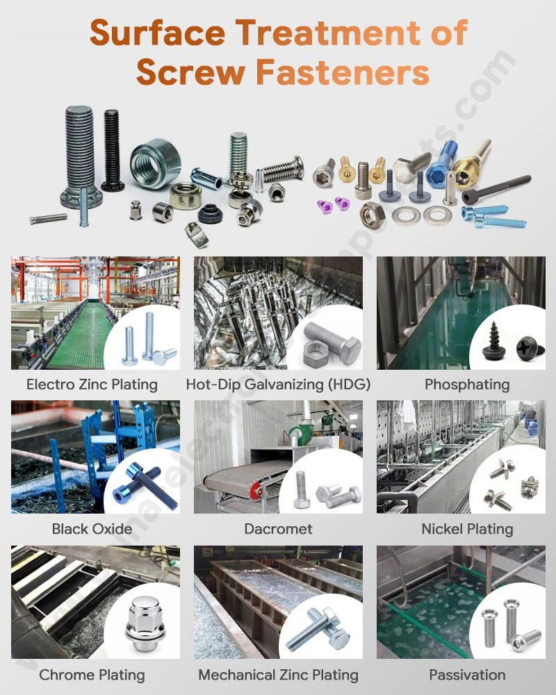
IATF 16949 Quality Control for Threaded and Staked Relay Yokes
An integrated process requires a control plan covering both dimensional characteristics and mechanical performance. A visually acceptable relay yoke may still contain an incomplete thread, insufficient fastener retention or an internal defect that becomes apparent only during assembly.
Quality verification should therefore combine in-process monitoring, dimensional inspection and functional testing.
Recommended inspection and validation matrix
| Quality characteristic | Inspection method | Control stage | Record or output |
| Hole diameter | Pin gauge or optical measurement | In-process | Dimensional inspection record |
| Thread size | GO/NO-GO thread gauge | In-process and final | Thread inspection record |
| Thread depth | Depth gauge or section analysis | In-process validation | Thread depth report |
| Thread pull-out force | Axial tensile test | Process validation | Pull-out test report |
| Stripping torque | Calibrated torque test | Process validation | Torque test report |
| Fastener insertion height | Height gauge or CMM | In-process and final | Dimensional report |
| Fastener retention | Pull-out test | Process validation and periodic audit | Retention test report |
| Fastener rotation resistance | Torque test | Process validation | Rotation resistance report |
| Yoke flatness and profile | CMM or optical measurement | Final inspection | Dimensional inspection report |
| Burr condition | Optical inspection or specified burr measurement | In-process and final | Visual or dimensional record |
CMM inspection and datum-based measurement
For precision relay yokes, dimensional inspection should use a defined datum structure based on the component drawing. Measuring thread position, fastener height and formed profiles without a consistent datum can produce misleading comparisons between samples.
CMM inspection can verify:
Thread center position relative to the yoke datum.
Fastener location and perpendicularity.
Mounting-hole relationships.
Formed profile dimensions.
Flatness and positional tolerances.
The measurement method and equipment resolution must be appropriate for the drawing tolerance. A CMM report should identify the datum alignment, measured characteristics and actual results rather than presenting a single overall pass statement.
IATF 16949 process documentation and PPAP
For automotive relay and contactor supply chains, customer-specific quality requirements may include APQP, PFMEA, Control Plan, MSA, SPC and PPAP.
An integrated tapping and staking process should be represented in the process flow and PFMEA. Potential failure modes include:
Tap breakage or incomplete thread forming.
Incorrect pre-hole diameter.
Missing or reversed fastener.
Insufficient staking deformation.
Excessive staking deformation.
Thread or fastener position outside drawing tolerance.
Tool wear causing gradual dimensional drift.
Where PPAP Level 3 is requested, the submission package should be prepared according to the customer's applicable requirements and agreed submission scope. It may include dimensional results, material documentation, process flow, PFMEA, Control Plan, MSA, capability studies and functional test evidence.
Request a Relay Yoke Manufacturing Review
Engineering Design Inputs for In-Die Tapping and Fastener Staking
Early design review is essential because the feasibility of in-die operations depends on the relationship between material properties, sheet thickness, hole geometry and fastening requirements.
A component drawing intended for conventional secondary tapping may require adjustments before it can be transferred to an integrated progressive die process.
Drawing information required for DFM evaluation
| Design input | Why it is required |
| Steel grade and material specification | Determines ductility, hardness and forming response |
| Sheet thickness and tolerance | Establishes available thread engagement and staking material |
| Thread size, pitch and class | Defines forming tap geometry and inspection requirements |
| Pre-hole diameter | Determines material displacement and thread formation |
| Thread depth | Defines required engagement and forming stroke |
| Fastener type and material | Determines insertion method and mechanical compatibility |
| Fastener retention requirement | Defines staking geometry and validation tests |
| Critical datum dimensions | Establishes tooling references and inspection alignment |
| Annual production volume | Supports the decision between integrated and separate operations |
| Customer quality requirements | Defines PPAP, inspection and traceability scope |
When in-die tapping is not the preferred solution
In-die tapping should not be selected solely to reduce the number of operations. Separate tapping or alternative fastening methods may be more appropriate when:
The sheet material lacks sufficient ductility for thread forming.
The available material thickness cannot provide the required thread engagement.
The thread location is inaccessible within the proposed die layout.
The design requires frequent thread-size changes.
Production volume does not justify integrated tooling investment.
The required thread strength is better achieved through a separate insert or thicker mounting feature.
A technically sound DFM review should compare the total manufacturing cost, inspection burden, tooling maintenance and assembly performance-not only the number of process steps.
FAQ: In-Die Tapping and Relay Yoke Fastener Staking
1. Can roll forming taps produce internal threads in cold-rolled electrical steel relay yokes?
Yes, provided the steel grade, hardness, sheet thickness and pre-hole diameter are suitable for thread forming. Material-specific trials should confirm forming torque, thread geometry, tool life and mechanical performance.
2. How is thread pull-out strength verified in an in-die tapping process?
Thread pull-out strength is verified through axial tensile testing using the specified fastener and engagement conditions. Thread size, depth and material thickness should also be inspected to identify the cause of any failure.
3. Can automated fastener insertion and staking be included in the same progressive die as relay yoke stamping?
Yes. A progressive die can combine punching, forming, thread forming, fastener insertion and staking when tooling access, feeder synchronization, press capacity and component geometry permit. Validation must include fastener position and retention testing.
contact us
Send Inquiry