



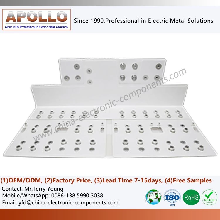
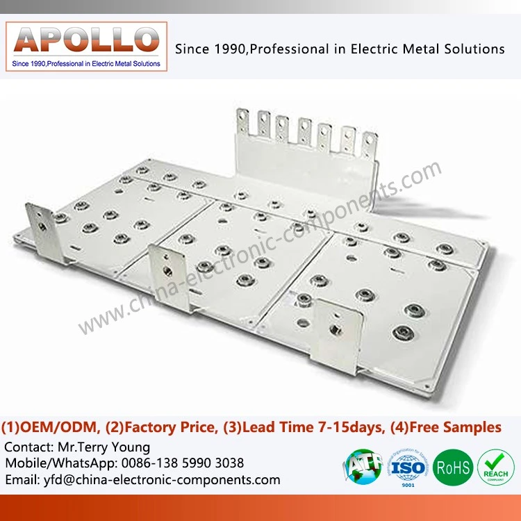
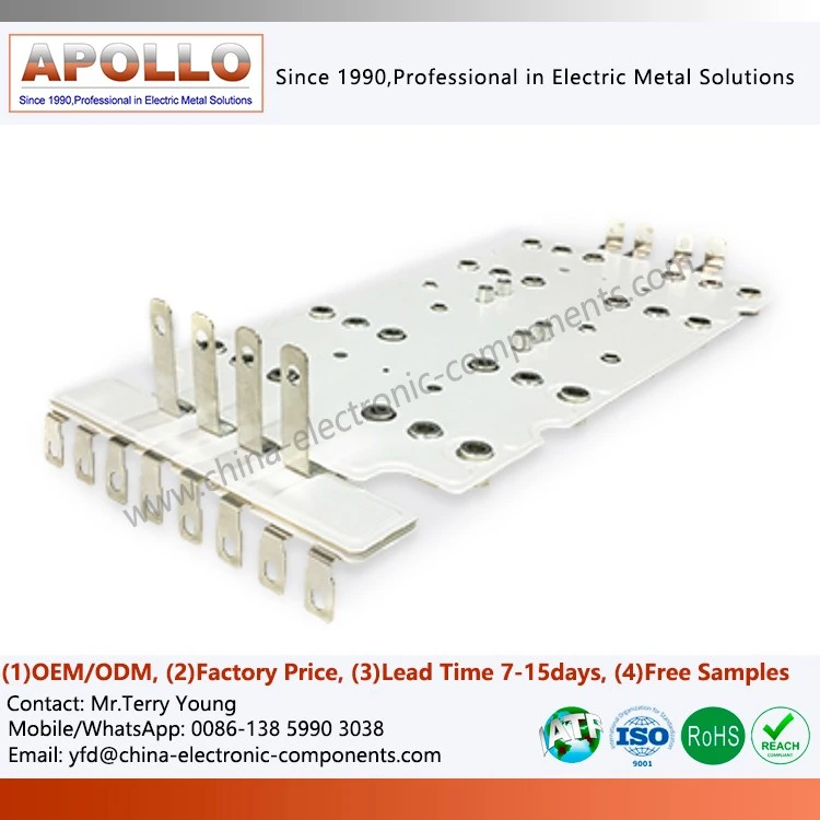
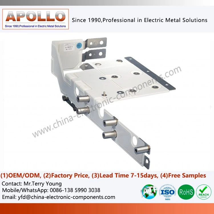
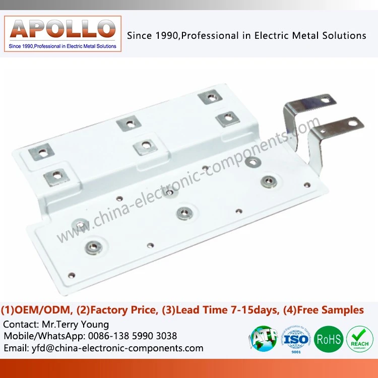
Laminated Bus Bar For Spacecraft Power Inverter
What is a Laminated Bus Bar for Spacecraft Power Inverter?
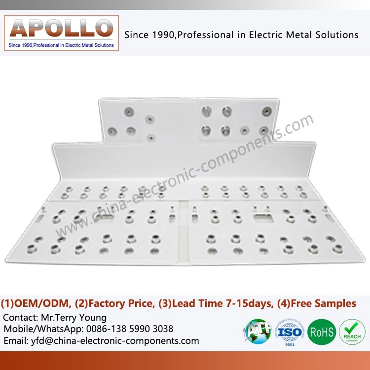
Compared to busbar systems used in ground-based power applications, aerospace-grade laminated busbars offer an advantage not in terms of higher current-carrying capacity, but in terms of deterministic reliability:
Protection against low-pressure discharge: According to Paschen's Law, low-pressure environments represent the most critical regime for gas discharge. We mitigate the risk of partial discharge in vacuum conditions by increasing insulation clearance, employing a stepped creepage path design, and homogenizing electric fields at the edges.
Fretting-resistant terminations: Vibrations during launch and on-orbit operations can induce micron-scale relative sliding at terminal interfaces. By utilizing silver- or gold-plated composite coatings and strictly controlling surface roughness, we suppress fretting wear and prevent drift in contact resistance.
Lightweight design without compromising current capacity: Through topological optimization of copper and insulation thicknesses-distributing material strategically along current paths rather than applying uniform thickening-we achieve an optimal balance between mass and current-carrying capacity.
Material Advantages
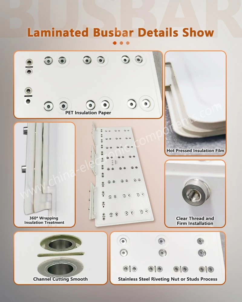
Materials are the first threshold for aerospace BusBar with PET Insulating Paper reliability. We follow a strict selection principle: every material must have proven flight heritage or equivalent validation data.
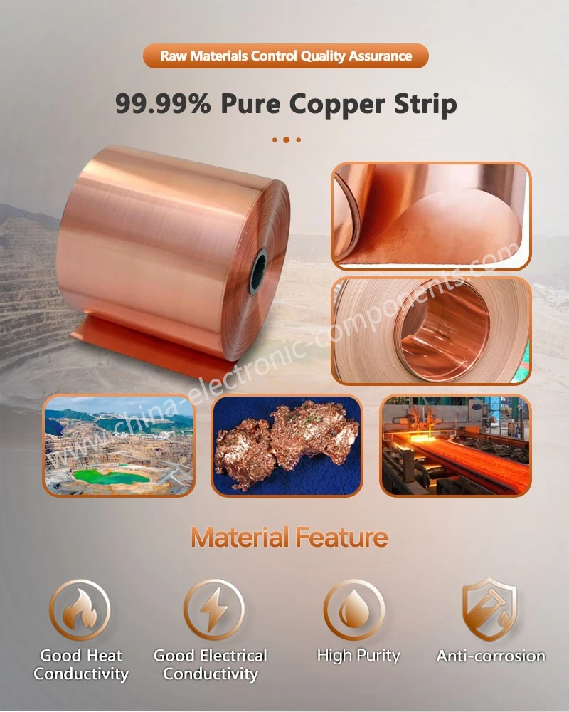
Conductor Materials
We utilize high-purity oxygen-free copper, balancing electrical conductivity with creep resistance. To meet weight-reduction requirements, we offer copper-clad aluminum (CCA) conductors, which optimize the mass budget while maintaining current-carrying capacity.
Insulation Dielectrics
We employ radiation-resistant polyimide and modified polyester film systems, with outgassing characteristics that meet the stringent entry requirements for materials used inside spacecraft cabins.
Surface Treatments
Options include nickel plating, silver plating, or electroless tin plating. With uniform and precisely controlled coating thickness, these treatments ensure stable contact resistance, excellent solderability, and resistance to sulfidation.
Potting and Coating
We provide space-grade conformal coatings and stress-buffering potting compounds, further enhancing protection against vacuum discharge and mechanical stress.
Application Advantages for Laminated Bus Bar for Router Backplane Distribution
Spacecraft Power Inverters
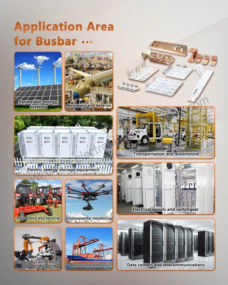
These applications demand low inductance, low loss, lightweight design, and long-term stability within the power conversion circuit. Laminated busbar structures address both electrical and thermal management challenges simultaneously within compact spaces. Additional environmental and insulation verification can be performed in accordance with customer-specified high-reliability or aerospace-grade standards.
UPS and Server Power Supplies
This is the most mature and primary domain for laminated busbars. As requirements for power density and efficiency continue to rise, laminated solutions help shorten busbar lengths, reduce temperature increases and operational noise, and improve assembly consistency across the entire unit.
Extended Applications
Medium-to-high-power conversion equipment, including inverters for photovoltaics and energy storage systems, industrial variable-frequency drives (VFDs), auxiliary power systems for electric vehicles and rail transit, medical power supplies, and power sources for testing and experimentation.
Everything You Need to Know about Laminated Busbars: Passive Electronic Components
1. What are the fundamental differences between laminated busbars and traditional copper busbars?
Traditional copper busbars consist of a single conductor with external insulation, making it difficult to control loop area and parasitic parameters. In contrast, laminated busbars integrate positive and negative conductors with insulating layers into a single, stacked assembly. This structural design reduces the loop area and incorporates mechanical support and safety features, making them better suited for high-frequency, high-power-density converters.
2. Can these laminated busbars be used in power inverters for spacecraft?
Yes, they can be designed and verified to meet high-reliability requirements. Laminated structures offer advantages in terms of low stray inductance, weight reduction, and thermal management. The specific material system, insulation class, and additional test requirements are determined based on the client's specified standards and mission profile.
3. What information is required for custom development?
Typically, you will need to provide the circuit topology and commutation loop details, current and voltage ratings, component models and layout, installation space and interface specifications, insulation and safety requirements, as well as environmental and service life requirements. The more comprehensive the information provided, the more accurate the laminated busbar design and simulation results will be.
4. How are interlayer insulation and the risk of partial discharge managed?
This is addressed through three key aspects: matching insulating materials with appropriate temperature ratings; optimizing the edge geometry and sealing of the layers to prevent electric field concentration; and ensuring high-quality interlayer bonding through controlled curing parameters and process documentation. If necessary, partial discharge testing can also be performed in accordance with client requirements.
contact us
If your Laminated Busbar for Three Level Inverter design is currently in the selection phase-prior to the finalization of the mission profile-we invite you to submit your specifications (including stack-up topology, terminal interfaces, and acceptance criteria) via our inquiry page. Our engineering team will conduct an initial review covering electrical, thermal, and mechanical manufacturability, ultimately delivering a customized solution that is fully verifiable, traceable, and compliant with all specified requirements.
Hot Tags: Laminated Bus Bar for Spacecraft Power Inverter, Spacecraft Power Inverter Busbar, Laminated DC Busbar, Power Inverter Busbar, IGBT Busbar, laminated busbar, Lamination Busbar, Multilayer Busbar, Traffic Tram Electric BusBar, Web Server BusBar
You Might Also Like


Send Inquiry