










Technical Analysis Of Laminated Busbar Insulation Materials: Performance Differences And Application Selection Between Flexible And Rigid Insulation
Oct 09, 2026
Leave a message
With the advancement of new energy vehicles, power electronics, industrial variable-frequency drives, and high-power energy conversion equipment, the structural design of laminated busbars has evolved from simple conductive interconnection toward the synergistic optimization of electrical insulation, mechanical structure, thermal management, and spatial layout. Insulation materials not only influence the busbar's voltage withstand capability, creepage performance, and long-term operational reliability but also determine interlayer spacing, structural compactness, and manufacturing processes. The appropriate selection of flexible and rigid insulation materials is crucial for meeting requirements regarding voltage levels, operating temperatures, and application environments.
Basic Structure and Application Principles of Laminated Busbar Insulation Materials
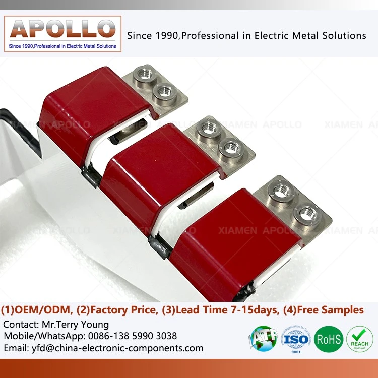
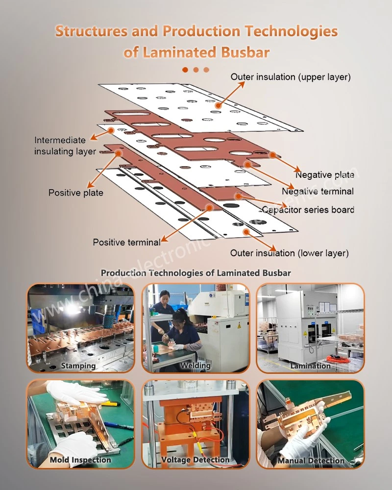
Laminated busbars typically consist of multiple layers of copper or aluminum conductors, interlayer insulation materials, and necessary structural supports. By stacking conductors of positive and negative polarities-or those at different potentials-in a specific design sequence and isolating adjacent conductors with insulation layers, the spatial footprint of the current loop is reduced, stray inductance is lowered, and the integration of electrical connections is enhanced.
Within this structure, insulation materials perform three primary functions. First, they isolate conductors at different potentials to prevent interlayer short circuits and electrical breakdown. Second, they provide necessary insulation protection at conductor edges, mounting holes, and terminal areas, thereby mitigating the risks of local electric field concentration and discharge. Finally, through their mechanical strength, heat resistance, and dimensional stability, they maintain the busbar's structural integrity during assembly, vibration, and thermal cycling.
Based on structural form and application method, laminated busbar insulation is generally categorized into flexible film insulation and rigid insulation boards. Flexible insulation is primarily used for conductor surface coating, lamination, and edge sealing, whereas rigid insulation serves to provide structural isolation, support, and spacing control between conductive layers.
These two types are not mutually exclusive alternatives; rather, they are used in combination based on the product's voltage rating, structural dimensions, and manufacturing specifications. For instance, in high-density data center power distribution architectures, laminated busbars for supercomputer circuit boards or backplanes must address the constraints of limited installation space while managing electrical isolation, conductive path layout, and assembly precision; consequently, the thickness of the insulation layer and the spacing between conductors must strike a balance between electrical safety and structural compactness.
Common Flexible Insulation Materials and Their Performance Characteristics
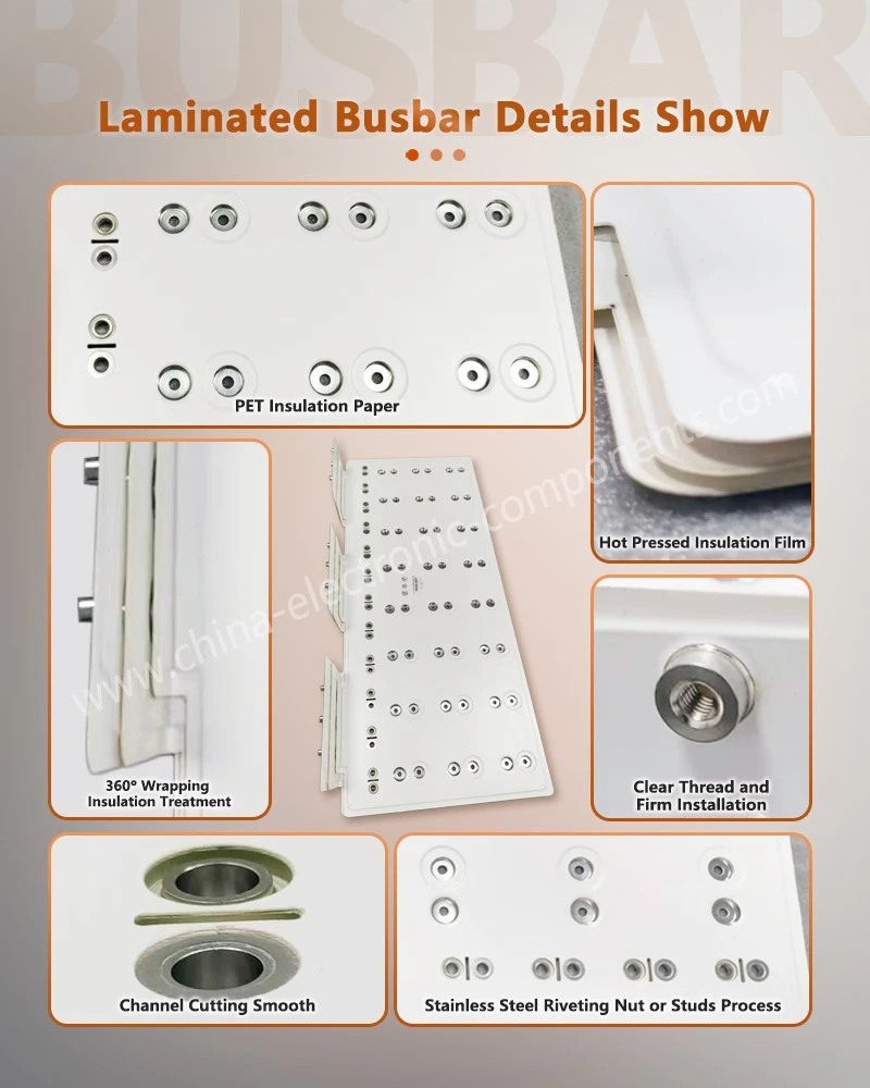
Flexible insulating films are typically bonded to conductor surfaces via lamination, hot pressing, or other suitable processes. These materials must exhibit excellent electrical insulation, heat resistance, ductility, and interfacial bonding properties to withstand conductor bending, stamping, and subsequent assembly operations.
Polyethylene terephthalate (PET) is a common flexible insulation material used in laminated busbars. It offers good processability, effective surface insulation, and cost-efficiency, making it suitable for electrical interconnection structures operating within standard temperature ranges. By selecting the appropriate film thickness and lamination process, the insulation material can be made to conform closely to the conductor surface and effectively cover the conductor edges.
The specific temperature resistance of PET film depends on the material grade, film thickness, adhesive system, lamination process, and actual operating conditions. During design, the continuous operating temperature should not be determined solely by the material name; instead, one should consult the supplier's temperature ratings, long-term aging data, and validation results for the complete assembly.
Another advantage of PET is its good ductility. During conductor bending or edge wrapping, a suitable film can accommodate a certain degree of deformation, thereby reducing the risk of the insulation layer cracking, tearing, or thinning locally. However, damage to the insulation layer can still occur if the bending radius is too tight, conductor edges are excessively sharp, or forming pressures are improper; therefore, careful control is required during the mold design and forming process stages.
Polyimide (PI) film is primarily used in specific applications requiring superior heat resistance. Compared to standard PET, PI generally offers higher thermal resistance, making it suitable for busbar structures involving localized welding, thermal processing, or exposure to elevated temperatures. However, the ductility, surface electrical properties, and processing costs of PI must be evaluated based on specific grades; one cannot simply assume it outperforms PET in every performance aspect.
For power distribution equipment-specifically laminated busbars for power distribution backplanes-the selection of insulation materials requires a comprehensive assessment of operating voltage between conductors, temperature rise, installation space, and manufacturing methods. If the product involves localized welding, the impact of welding heat on the film, adhesive, and interfacial bond strength must also be evaluated to prevent thermal damage or delamination of the insulation layer during processing.
Differences and Integration of Flexible and Rigid Insulation
The primary differences between flexible and rigid insulation lie in their mechanical form, structural function, and processing methods.
Flexible insulation typically takes the form of a film covering the conductor surface, focusing on conductor encapsulation, electrical isolation between layers, and edge sealing. It is relatively thin, capable of accommodating a certain degree of bending and complex contours, making it suitable for busbar designs that require compact structures and high space utilization.
Rigid insulation usually employs insulating sheets with sufficient mechanical strength to support conductors, maintain interlayer spacing, and prevent unintended contact during assembly. Common materials include glass fiber-reinforced epoxy resin sheets, glass fiber-reinforced polyester materials, and other electrical insulating sheets that meet design specifications. Specific material selection depends on operating temperature, dielectric properties, mechanical loads, and environmental conditions.
In practical applications, flexible films and rigid insulation sheets are often used in combination. The film provides insulation protection for conductor surfaces and specific edges, while the rigid material offers necessary structural isolation and support. Together, they form a complete insulation system; its performance depends not only on the materials themselves but also on lamination quality, conductor edge profiles, assembly tolerances, and connection structures.
For instance, laminated busbars used in cellular base station power distribution must arrange multiple power conductors within a limited space while ensuring electrical safety and mechanical stability during equipment operation. Designers should reasonably determine the coverage area of flexible film insulation and the placement of rigid isolation structures based on voltage levels, conductor layout, and installation methods.
It should be noted that insulation thickness cannot be calculated simply by applying a fixed "millimeters per kilovolt" rule. Actual design must take into account the rated operating voltage, transient overvoltage, the dielectric strength of the insulation material, partial discharge requirements, pollution degree, altitude, and applicable standards. For high-voltage applications, the safety margin of the insulation structure must also be verified through necessary electrical calculations and testing.
Key Technical Parameters for Insulation Material Selection
Selecting insulation materials for laminated busbars requires a comprehensive evaluation of thermal rating, dielectric strength, Comparative Tracking Index (CTI), elongation, mechanical stability, and flame retardancy. Since these parameters are interrelated, the suitability of a material cannot be determined based on a single indicator alone.
The Relative Thermal Index (RTI) is used to evaluate a material's ability to maintain specific properties under conditions of long-term thermal exposure.
Evaluations typically distinguish between electrical and mechanical properties; therefore, when selecting materials, one must verify the specific performance category and test conditions associated with the data. RTI does not equate to the maximum temperature at which a material can operate continuously under all conditions; actual application requires consideration of thermal cycling, localized temperature rise, environmental conditions, and material aging mechanisms.
Dielectric strength represents a material's resistance to dielectric breakdown and is generally dependent on specimen thickness, test methods, temperature, and environmental conditions. Designers should evaluate this based on actual voltage stress, insulation thickness, and the electric field distribution within the structure, rather than simply equating a single dielectric strength value from a material sample to the withstand voltage capability of the finished product.
The Comparative Tracking Index (CTI) evaluates the ability of an insulation material's surface to resist tracking under specified test conditions. This parameter is particularly critical for electrical equipment exposed to moisture, contamination, or risks of surface conductive paths. CTI is not directly equivalent to creepage distance; the actual required creepage distance depends on operating voltage, pollution degree, material group, and applicable electrical safety standards.
Elongation reflects a material's ability to deform before fracturing when subjected to tensile stress. For insulating films that must wrap around conductor edges, conform to complex contours, or undergo thermoforming, ductility influences the processing window and the consistency of the finished product.
If conductor edges feature burrs, notches from punching, or sharp corners, localized damage may occur during the forming process, even if the film itself possesses high elongation.
Flame retardancy ratings are used to evaluate a material's combustion behavior under specified test conditions. When selecting materials, one must verify the specific material grade and its certification status; the typical properties of a material category cannot be assumed to apply to all materials within that same class.
In power architectures for communication equipment-such as laminated busbars for router backplane distribution-designs must balance electrical isolation between multiple conductors, long-term temperature rise, and compact layout requirements. Consequently, material selection must address dielectric properties, flame retardancy, and structural stability post-lamination.
Differences in Insulation Design: Industrial Power Equipment vs. Automotive Applications
Different application sectors exhibit distinct requirements regarding operating voltage, service life, temperature fluctuations, vibration conditions, and insulation validation; therefore, identical material and structural designs cannot be applied across the board for laminated busbars.
Industrial power equipment typically operates over long lifecycles, with some systems functioning under conditions of high voltage, high current, and continuous load. Designers must consider not only steady-state operating voltage but also factors such as switching transients, overvoltage, insulation aging, and long-term thermal cycling. For medium- and high-voltage systems, partial discharge, creepage distance, and electrical clearance are often critical constraints in insulation structure design.
For instance, busbars in power distribution units (PDUs) handle multi-channel power transmission; their insulation systems must satisfy requirements for conductor isolation, structural support, and environmental adaptability. In compact designs, flexible insulating films may be used to cover conductor surfaces, while rigid insulating components maintain necessary physical clearances.
Automotive applications place greater emphasis on volume, weight, vibration resistance, temperature cycling, and mass-production consistency.
Electric drive systems, onboard charging equipment, and battery-related electrical components in new energy vehicles often face simultaneous constraints involving high currents, rapid switching, and limited installation space. Therefore, insulation materials must be designed in coordination with the busbar conductor shape, welding locations, connection terminals, and the overall thermal management strategy of the unit.
For motor controller busbars, material selection must account not only for dielectric strength between conductors but also for internal temperature rise, vibration, and assembly space constraints. If the structure involves localized welding or other thermal processing, the insulation layer's ability to withstand the resulting thermal impact must also be verified.
In Uninterruptible Power Supply (UPS) systems, busbars must meet electrical safety requirements for power switching, continuous operation, and fault conditions. Insulation design verification should incorporate system rated voltage, overload conditions, thermal distribution, and equipment standards to ensure material performance aligns with the actual operating environment.
Considerations for Insulation Material Application in Various Industrial Scenarios
In the rail transit sector, busbars are typically subjected to vibration, shock, temperature fluctuations, and sustained electrical loads. Beyond meeting basic dielectric strength requirements, insulation designs must address mechanical mounting methods, material aging, and the risk of damage during maintenance. For composite busbars used in train power supply four-quadrant power modules, the insulation solution must accommodate the module's connection layout, heat dissipation structure, and installation space, with verification performed according to specific vehicle system requirements.
In the telecommunications power sector, multi-channel power distribution structures impose stringent requirements regarding insulation material thickness, manufacturing precision, and flame retardancy. For laminated busbars used in telecom power distribution, appropriate film and support materials must be selected based on system voltage, internal equipment space, and long-term operating temperatures, while ensuring adequate insulation protection at connection points and conductor edges.
Rack-mounted power equipment often requires multi-channel power delivery and modular assembly within limited space. Key design considerations for laminated busbars in rack-mounted power distribution include interlayer insulation, conductor layout, mounting structures, and assembly tolerances. For equipment requiring frequent maintenance or module replacement, the impact of disassembly and reassembly on insulation layers and connection points must also be evaluated.
Power conversion units in medical imaging equipment may involve high-power supplies, precision control systems, and specific safety requirements. When selecting materials for laminated busbars used in medical imaging and testing devices, one must consider the equipment's electrical architecture, operating environment, temperature rise, and relevant safety standards, rather than relying solely on voltage withstand ratings.
Power modules in stage lighting systems often feature compact layouts, frequent start-stop cycles, and significant localized temperature rises. In practical applications, the heat resistance, flame retardancy, and assembly compatibility of the insulation materials must be carefully evaluated, and their suitability confirmed based on the specific product structure.
For high-density power delivery architectures in network equipment (such as internet router backplanes), laminated busbars require a balance between space utilization, conductive paths, and electrical isolation. Insulation thickness, conductor spacing, and connection point locations should be determined by considering both current paths and heat dissipation requirements to minimize conflicts between structural design and subsequent assembly.
Other Insulation Processes and Their Applicability
In addition to flexible film lamination and rigid insulation boards, processes such as powder coating, epoxy resin coating, and other insulation encapsulation methods can be applied to specific conductor structures. These processes are selected based on part geometry, insulation requirements, and manufacturing conditions, though their scope of application differs from that of laminated insulation.
Powder coating can cover complex metal surfaces and is suitable for conductors or metal components requiring a surface insulation layer. Its actual insulation performance depends on the coating material, film thickness uniformity, edge coverage quality, curing conditions, and substrate pretreatment. Particular attention should be paid to sharp corners, holes, and narrow areas to check for issues such as excessively thin coatings, pinholes, or incomplete coverage.
Epoxy resin coating and potting processes can provide localized insulation, moisture resistance, and structural protection; however, factors such as curing shrinkage, differential thermal expansion, interfacial bonding, and long-term thermal aging must be evaluated. If the conductor generates continuous heat during operation, the difference in thermal expansion between the coating and the metal may affect long-term reliability; therefore, verification through appropriate environmental testing is essential.
Compared to laminated films, surface coatings generally rely more heavily on the uniformity of the coating process and the quality of edge treatment; furthermore, coatings differ from rigid insulating boards in their ability to provide structural support and maintain conductor spacing. Therefore, the choice of process should be based on the complete electrical connection structure.
Key Quality Control Points for Laminated Busbar Insulation Design
Selecting insulation materials is merely the starting point of the design process; ultimate performance depends on the manufacturing process and finished product verification. During production, critical control points include conductor burrs, edge chamfering, film positioning, lamination pressure, temperature profiles, adhesive curing status, and the integrity of the insulation layer coverage.
For laminated structures, inspections should check for air bubbles, wrinkles, misalignment, delamination, or localized damage in the film, and confirm adequate insulation coverage around conductor edges and mounting holes. For busbars incorporating rigid spacers, dimensions, assembly spacing, and fastening methods must be verified to prevent localized electric field intensification or insufficient insulation clearance caused by assembly deviations.
Finished product verification should be determined based on the product's rated voltage, application environment, and relevant standards; this may encompass tests such as insulation resistance, withstand voltage, temperature rise, thermal cycling, mechanical vibration, and partial discharge. Not all products require the exact same suite of tests; specific test protocols should be determined based on a combination of system risk, product specifications, and applicable standards.
Furthermore, factors such as insulation material batches, supplier changes, film thickness adjustments, and variations in process parameters can all impact product performance. Establishing mechanisms for material traceability, process documentation, and change verification helps minimize performance fluctuations during mass production and enhances the predictability of long-term product operation.
Future Trends in Laminated Busbar Insulation Technology
As power electronics equipment evolves toward higher power density, higher switching frequencies, and greater compactness, laminated busbar insulation design will increasingly prioritize the synergistic optimization of materials, structures, and manufacturing processes.
On one hand, insulation materials must strike a more balanced compromise between heat resistance, dielectric properties, mechanical strength, and processability. On the other hand, as system voltages and switching speeds rise, greater attention will be focused on local electric field distribution, interlaminar air gaps, conductor edge geometry, and the risk of partial discharge.
Meanwhile, technologies such as automated lamination, precision die-cutting, in-line visual inspection, and electrical performance testing will help improve manufacturing consistency for insulation structures. By systematically managing material batches, processing parameters, and finished-product test results, the manufacturing process can identify potential defects at an earlier stage, thereby reducing rework and the risk of batch-wide quality issues.
Overall, the insulation design for laminated busbars is not merely a matter of increasing insulation thickness; rather, it involves establishing appropriate design parameters that balance electrical safety, thermal stability, mechanical reliability, and structural compactness. Determining the suitable flexible films, rigid insulating materials, and their specific combinations requires consideration of the operating voltage, service environment, manufacturing processes, and validation requirements.
For engineering procurement and project selection, it is recommended that specifications-including rated voltage and current, operating temperature, installation space, insulation requirements, and the intended application environment-be provided during the inquiry stage. This enables suppliers to evaluate the material configuration, structural design, and validation plan for the laminated busbars accordingly.
contact us
Send Inquiry