

Laminated BusBars Stray Inductance Optimization Guide: How To Reduce Voltage Spikes And Switching Losses in SiC Inverters
Jun 18, 2026
Leave a message
In the transition of power electronic systems from traditional silicon IGBTs to silicon carbide (SiC) devices, a key issue has gradually emerged: SiC devices have extremely fast switching speeds, but stray inductance in the system can severely hinder performance. Voltage spikes and high-frequency oscillations caused by stray inductance not only threaten device safety but also significantly diminish the performance advantages of SiC. High-density Laminated Busbars are the core structural solution to address this bottleneck. This article will explain why Laminated Busbars can reduce inductance and how to select them in practical applications.

I. While SiC devices are faster, stray inductance becomes a major obstacle.
SiC MOSFETs switch at speeds more than ten times faster than silicon devices, resulting in higher power density and efficiency. However, the other side of the coin is that faster switching leads to a higher rate of change of current (di/dt). According to the formula V = L × di/dt, even a stray inductance of only a few nanohenries can generate voltage spikes of hundreds of volts across the device. These spikes superimposed on the bus voltage, and if they exceed the device's withstand voltage limit, they will break down and burn out.
More problematic is that stray inductance can also resonate with the output capacitance of SiC devices, generating high-frequency oscillations (ringing). This oscillation increases switching losses and causes the device to heat up, and also generates severe electromagnetic interference, preventing the system from passing EMC certification. For safety, engineers often have to compromise: either choose modules with higher withstand voltage (increasing cost and losses) or increase the gate resistance to slow down the switching speed (directly wasting the high-frequency advantage of SiC). The emergence of three-layer laminated busbars aims to eradicate this problem at the structural level.
II. Why does a laminated busbar in a high-power converter reduce inductance?
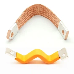
Traditional busbars have two separate conductors, with forward and reverse currents far apart. The magnetic fields they generate cannot cancel each other out, resulting in high stray inductance. The core idea of a laminated busbar in a high-power converter is to stack the forward and reverse conductors together, making them run very close together. The current directions are opposite, and the magnetic field directions are also opposite; the two magnetic fields cancel each other out, reducing stray inductance to one-tenth or even less of traditional solutions.
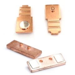
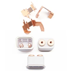
From a product classification perspective, laminated bus bars are not ordinary conductive busbars, but rather passive power components with a precisely designed structure. Depending on the number of layers, common structures include three, four, or even five layers. The more layers, the more compact the current path and the lower the inductance. As a key connection component in the inverter, its inductance value directly determines the upper limit of the entire inverter's dynamic performance.

III. How to Select Laminated Bus Bars for Different Application Scenarios?
The core logic for selection is: first consider the voltage level, then the current capacity, and finally the installation space.
New energy vehicles are currently the fastest-growing application area for lambinated bus bars. Laminated bus bars for electric cars need to carry hundreds of amperes of current within a very small space while meeting automotive-grade vibration and temperature cycling requirements. They typically employ multi-layer composite structures to balance low inductance and high reliability.
The rail transit sector has extremely high safety requirements. Subway lambinated bus bars must meet stringent standards for explosion-proof, fire-proof, and corrosion-proof protection, while controlling electromagnetic interference in the enclosed environment of underground tunnels. Therefore, products with protective designs, such as High Voltage Explosion-Proof Inverter Busbars, are often chosen.
For complex topologies such as three-level inverters, lambinated bus bars for three-level inverters need to integrate multiple positive and negative buses within a single busbar, resulting in higher structural complexity and more stringent requirements for interlayer insulation and alignment accuracy. Laminated Busbars for complex Busbar Installations are designed for industrial frequency converters, energy storage systems, and other applications, and support customized multi-branch designs.

IV. Key Design Considerations for Laminated Copper Busbars
A good laminated copper busbar is essentially a multi-layer composite structure connection bar. Its design focuses on three key aspects: First, the interlayer insulation must be reliable, and the withstand voltage rating must match the system voltage. Second, the alignment accuracy of the positive and negative conductors must be controlled within millimeters; the greater the misalignment, the worse the magnetic field cancellation effect. Third, the heat dissipation path must be unobstructed, because low inductance does not equal low heat generation; the temperature rise of the copper busbar itself under high current still needs to be managed. The final performance of a laminated low-inductive busbar is the combined result of these three indicators.
For customized solutions or technical selection support for laminated copper busbars, please contact us. We will provide a professional quote based on your voltage, current, and installation scenario.
contact us

Send Inquiry