










Layout and Redundancy Design Essentials for Busbar Power Distribution Systems in Data Center Server Rooms
Oct 09, 2026
Leave a message
As cloud computing, artificial intelligence, and high-performance computing continue to evolve, the power density of data center racks is steadily rising. Consequently, power distribution systems face increasingly stringent requirements regarding continuous operation, space utilization, thermal management, and maintenance efficiency. As a key method for end-of-line power distribution, busway systems-comprising busway trunking, feed-in units, and tap-off boxes-create flexible power distribution paths.
They reduce the need for extensive traditional cabling and facilitate rack capacity expansion and load adjustments. An optimal busway layout requires a holistic approach that considers power distribution architecture, redundancy, rack arrangement, cooling methods, communication cabling, and fire safety regulations, ensuring the system delivers the necessary current-carrying capacity while maintaining high levels of safety and maintainability.
Basic Architecture of Data Center Power Distribution Systems
Data center power distribution systems are typically categorized into three tiers: utility/grid-side distribution, facility-level distribution, and end-of-line distribution. The utility-side distribution tier consists primarily of high- and low-voltage distribution equipment, transformers, and backup power generation systems; it is responsible for receiving and converting external power to supply the entire data center.
The facility-level distribution tier generally includes low-voltage distribution cabinets, Uninterruptible Power Supply (UPS) systems, and related equipment, handling power distribution, voltage conversion, and supply reliability. Finally, the end-of-line distribution tier delivers power-via row-end cabinets or busway systems-to the Power Distribution Units (PDUs) within the racks, ultimately powering servers, switches, storage devices, and other critical loads.
In high-density data centers, the design of the end-of-line distribution system directly impacts rack power capacity, space utilization, and operational efficiency. While traditional cable-based distribution relies on row-end cabinets and cable trays, busway distribution utilizes feed-in units, busway trunking, and tap-off boxes to form a continuous power supply channel, allowing for flexible placement of branch power points based on rack locations.
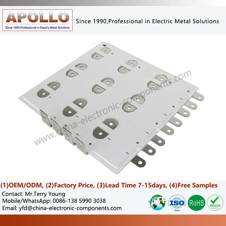
For facilities supporting high-power servers, GPU computing nodes, and centralized computing equipment, busway systems must also accommodate load fluctuations, localized temperature rises, and future expansion requirements. In high-performance computing scenarios, laminated busbars for supercomputer circuit boards or backplanes serve as a prime example of compact power connection structures. Their design focuses on shortening current paths and optimizing connection layouts, while determining conductor structures based on actual operating currents, insulation requirements, and available equipment space.
Data Center Power Redundancy and Busbar System Configuration
Data centers typically determine their power redundancy levels based on business criticality, availability targets, and fault recovery requirements. Common architectures include N, N+1, and 2N configurations. "N" represents the base equipment capacity required for normal operations; "N+1" adds a redundant unit to the base configuration to maintain power supply during partial equipment failure or maintenance; and "2N" employs two relatively independent power systems to provide dual-path power to critical loads.
In actual projects, redundancy design involves more than just the number of power sources; it requires evaluating the relationships between power distribution paths, protective devices, switching mechanisms, busbar branches, and cabinet power inputs. Even with dual power sources, if the two paths share a common point of failure at a critical node, the expected power reliability may not be achieved. Therefore, the design phase must clearly define the independence of the two power paths, load distribution methods, fault isolation strategies, and power supply boundaries during maintenance.
Cabinet-level power distribution typically utilizes dual A and B feeds. For servers with dual power inputs, the two feeds can be connected to separate power paths, allowing the equipment to continue operating via the second path should the first fail. Whether seamless switching can be achieved depends on the server's power supply design, load distribution, and system configuration; dual-path connectivity alone does not guarantee complete fault tolerance.
For server rooms utilizing UPS (Uninterruptible Power Supply) systems, the system busbars must be matched to the UPS output capacity, short-circuit protection configuration, and downstream load characteristics. Busbar rated current, short-circuit withstand capability, and connection structures should be verified against actual operating conditions and coordinated with the operating characteristics of upstream protective devices.
Types and Structural Characteristics of Server Room Busbar Systems
Based on capacity, installation location, and primary application, data center busbar systems can be categorized into power busbars used for main power distribution and server room busbars used for end-point distribution within the room. The capacity threshold distinguishing the two should be determined by the specific project design; a single current value should not serve as a universal classification standard. Server room busbars generally require low temperature rise, compact construction, flexible branch connection capabilities, ease of installation, and convenient maintenance; they are configured with appropriate conductor and insulation structures to meet AC or DC power supply requirements.
In terms of conductor arrangement and connection methods, common server room busbar structures include the sliding-rail type and the in-line type.
Sliding-rail busbars utilize a specific conductor layout to create a continuous connection channel, allowing for flexible placement of branch power points within a permissible range; this makes them suitable for scenarios requiring cabinet repositioning or the addition of end-point circuits. In-line busbars employ a multi-layer or parallel conductor structure with connection points spaced according to the design, offering a clear structural layout and straightforward manufacturing and installation processes. Specific selection requires a comprehensive assessment of rated current, number of branches, mechanical installation conditions, and operations and maintenance (O&M) practices.
For equipment requiring compact power distribution structures, "laminated busbars for power distribution backplanes" describe a solution using stacked conductive layers to connect to power backplanes. Such structures typically shorten current paths by alternating conductor and insulation layers, enabling power distribution within limited space; however, they still require validation regarding operating voltage, temperature rise, insulation durability, and connector layout.

Differences Between Busbar Power Distribution and Traditional Row-End Cabinet Distribution
The traditional row-end cabinet distribution model typically involves supplying power from a UPS or low-voltage distribution unit to a row-end cabinet, which then distributes power to cabinet PDUs via multiple cables. While this approach relies on a mature technical framework and suits existing server rooms or environments with mixed load types, the number of cables, required routing space, and circuit management complexity can increase significantly as the number of cabinets grows or power density rises. In a busbar power distribution setup, power is typically supplied from upstream equipment to the busbar's starting box; the busbar trunking then conveys power to plug-in boxes located along the line, which finally connect to the rack PDUs.
Compared to traditional methods, busbar systems reduce the need for long runs of end-circuit cabling and provide clearer branch power distribution points. When adjusting rack layouts or expanding capacity, power distribution changes can be made by repositioning plug-in units or adding branch components-provided the system design allows for it and necessary power-off, isolation, and safety verification procedures are completed.
However, busbar systems are not necessarily superior to end-of-row (EOR) cabinets in every project. For server rooms with fewer racks, stable layouts, or existing cabling infrastructure that still offers sufficient capacity, traditional solutions may better align with project costs and implementation conditions. Conversely, for newly built large-scale data centers, high-density server rooms, and facilities requiring ongoing expansion, it is worth prioritizing a comparison of busbar solutions against traditional methods regarding space utilization, installation workload, branch circuit management, and full-lifecycle maintenance.
Overhead and Under-floor Busbar Layouts
Busbars are typically installed either above the racks or beneath the raised (anti-static) floor. Overhead installation is a common approach suitable for server rooms with adequate ceiling clearance, overhead routing space, and appropriate structural support. Once the busbar is installed along the row of racks, branch circuits can be routed downward-or in other designed directions-from the plug-in boxes to connect to the rack PDUs. This method facilitates visual inspection of the busbar, identification of plug-in points, and routine maintenance checks, while also minimizing the use of under-floor space.
Overhead installation requires careful coordination of spatial relationships between rack heights, busbar mounting heights, cable trays, communication cables, lighting, HVAC ducts, and fire suppression systems. The design must allocate sufficient clearance for installation, plugging/unplugging, maintenance, and component replacement, while also verifying the load-bearing capacity of the building structure. For server rooms utilizing cold-aisle or hot-aisle containment, it is also necessary to ensure that the busbars and plug-in boxes do not obstruct airflow patterns, ceiling panel structures, or equipment maintenance access paths.
Bottom-mounted configurations typically involve installing busbars in the space beneath the raised floor; this approach is suitable for retrofitting existing server rooms or systems utilizing under-floor air supply cooling. While this method alleviates congestion among overhead facilities, it may encroach upon space reserved for under-floor cabling and airflow, potentially complicating inspections, operations, and component replacement. When opting for bottom-mounting, critical factors to evaluate include under-floor clearance, ventilation pathways, dust and moisture protection, accessibility for maintenance, and electrical safety requirements.
For server rooms requiring centralized management of multiple power circuits, the compact power distribution concept exemplified by rack-mount laminated busbars highlights the importance of co-designing equipment installation space and power connection pathways. Specific structural designs should be determined based on factors such as cabinet configuration, load classification, and installation constraints.
Overhead Layout Schemes for A and B Busbars
Depending on the number of power circuits and the cabinet arrangement, overhead busbars can be configured in various ways, such as parallel multi-circuit layouts or centralized arrangements. A common approach involves installing independent busbars for the A and B power feeds, creating a parallel layout of four busbars aligned with the cabinet rows. Two rows of cabinets can be assigned to the A and B power feeds respectively, with busbar branches supplying power to the dual PDUs within each cabinet.
The advantage of a parallel four-busbar layout lies in its clear power distribution paths and easily identifiable circuit coverage, which facilitates load analysis, fault localization, and maintenance management. For server rooms with large numbers of cabinets and complex load distributions, this scheme helps minimize confusion between different power paths. However, the increased number of busbars places higher demands on overhead space planning, support structure installation, and circuit labeling; consequently, routing, spacing, and maintenance clearances must be standardized during the initial design phase.
An alternative approach involves centralized power supply using two busbars or routing them to encircle the cabinet rows. Centralized layouts can reduce the number of feed-in boxes and upstream power cables required; however, they may increase the load on individual busbars and complicate the design regarding crossings over cold-aisle containment structures or other equipment zones. A ring-bus configuration can reduce redundant power supply paths within specific cabinet layouts; however, circuit segmentation, protection zones, and fault isolation methods must be clearly defined-minimizing the number of busbars should not be the sole design objective.
Scheme selection requires a comprehensive comparison based on factors such as the number of cabinets, power density, redundancy targets, the location of the feed-in unit, upstream cable routing, and maintenance requirements. A lower number of busbars does not necessarily equate to lower overall costs, as requirements for conductor cross-section, rated current, feed-in unit specifications, mounting brackets, and protective equipment will also vary.
Busbar Current-Carrying Capacity, Temperature Rise, and Insulation Design
Data center busbars continuously carry the operating current for servers and network equipment; therefore, current-carrying capacity and temperature rise control are critical aspects of the design. The rated current of the busbar should not be estimated based solely on the number of cabinets; instead, factors such as maximum power per cabinet, load simultaneity factor, power factor, supply voltage, ambient temperature, and future expansion needs must be considered. For high-density server rooms with significant load fluctuations, the impact of load variations on localized temperature rise and circuit operating conditions must also be evaluated.
Busbar conductor material, cross-sectional area, contact resistance, and connection structure all influence operating temperatures. The contact interface between the plug-in unit and the busbar is a critical area requiring close attention; insufficient contact pressure, installation misalignment, surface contamination, or long-term thermal cycling can all lead to increased contact resistance. During project acceptance and maintenance, connection status, tightening specifications, temperature rise performance, and protection configurations should be inspected in accordance with product requirements, and appropriate testing methods should be used to verify system compliance with design specifications.
Insulation systems must be designed based on rated operating voltage, transient overvoltage, pollution degree, installation environment, and insulation coordination requirements. For equipment utilizing a laminated conductor structure, the dielectric strength, heat resistance, mechanical stability, and long-term aging characteristics of the insulation materials all impact system reliability. When applied to telecommunications equipment, power backplanes, or high-density electronic systems, the design approach for laminated busbars must balance electrical conductivity, insulation clearance, and thermal management within limited space.
Furthermore, busbar systems must comply with applicable electrical safety standards and coordinate with grounding, overcurrent, and short-circuit protection schemes. For power distribution nodes subject to high fault currents, the short-circuit withstand capability of the busbars and their connecting components must be verified; product specifications should not be determined solely based on normal operating currents.
Applications of Busbars Across Various Equipment and Industries
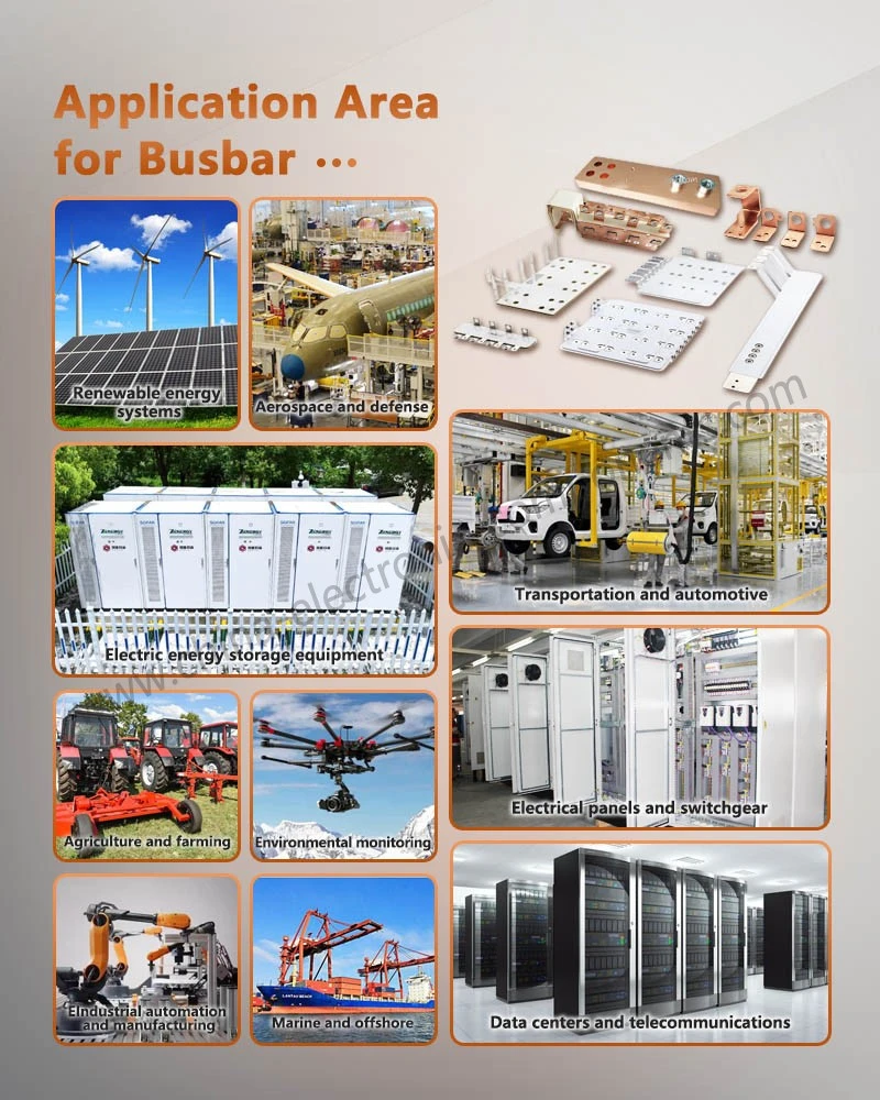
The application of busbar power distribution technology has expanded from traditional industrial power distribution to diverse sectors such as computing, telecommunications, transportation, and specialized equipment. Its core value lies in facilitating centralized power transmission and branched distribution through structured conductive paths, while simultaneously meeting equipment requirements regarding space, current-carrying capacity, and connection reliability.
In telecommunications infrastructure, laminated busbars for cellular base station power distribution exemplify compact power distribution solutions within base station power systems. Such equipment often requires the integration of rectifiers, backup batteries, and load circuits within limited cabinet space; consequently, the busbar design must balance ease of installation, insulation protection, and accessibility for future maintenance.
In network equipment and electronic systems, laminated busbars for router backplane distribution address the need for compact connection structures in power backplanes and internal power distribution. Designs must optimize conductor width, interlayer insulation, and connection methods by considering load currents, available space, terminal locations, and thermal management requirements.
For applications demanding high power stability and equipment integration-such as medical imaging devices-specialized busbar structures (e.g., for medical imaging testing devices) require designs tailored to operating voltages, peak loads, environmental conditions, and safety standards. These applications necessitate a particular focus on connection reliability, insulation performance, and electrical isolation measures during maintenance.
In the fields of motor drives and industrial automation, busbars for motor controllers facilitate conductive connections within the controller or between adjacent power units. For variable frequency drives, inverters, and other power electronic devices, busbar designs must also account for current loop length, parasitic inductance, switching transients, and electromagnetic compatibility (EMC) requirements. For rail transit and industrial power supply equipment-specifically regarding composite busbars used with four-quadrant power modules-design and validation must account for power module topology, operating environments, vibration conditions, and insulation requirements. Busbar materials, structural layer counts, and connection methods should be determined based on the specific electrical and mechanical conditions of each application scenario.
Key Points for Busbar Selection and Project Implementation in Data Centers
During the procurement and implementation phases of a busbar system, it is essential to first define the system voltage, rated current, number of circuits, installation orientation, and power supply redundancy. Additional requirements. Furthermore, interface compatibility between the feed-in unit, busway, tap-off box, and rack PDU must be verified to ensure that connection points, phase sequencing, protection methods, and installation dimensions meet design specifications. For data centers requiring future capacity expansion, planning should also address spare tap-off positions, busway capacity margins, and connection pathways for additional racks.
Before busway installation, on-site dimensions must be re-verified, and checks performed regarding rack layout, support positioning, overhead clearance, and potential spatial conflicts with other electromechanical systems. Installation must adhere to product technical documentation regarding support spacing, connection tightening, insulation testing, and phase sequence verification. Prior to system commissioning, necessary electrical tests, protection function checks, and load verification must be completed, alongside the establishment of circuit labeling and maintenance records.
During the operational phase, focus should be placed on load distribution, abnormal temperature rise, connection integrity, and the maintenance status of tap-off boxes. For dual-feed (A/B) power systems, the independence of the two power sources and load distribution must be regularly audited to prevent single-circuit overloads caused by load growth or equipment reconfiguration. Any capacity expansion or circuit adjustment requires engineering assessment and must be executed under prescribed safety conditions.
In summary, data center busway deployment is not merely a matter of installing conductors; it is a systems engineering task involving power distribution architecture, redundancy design, spatial planning, thermal management, electrical protection, and O&M workflows. A sound busway solution balances power reliability, space utilization, installation costs, and lifecycle maintenance, while allowing sufficient flexibility for future increases in rack power density.
For procurement teams planning to build or upgrade data center power distribution systems, it is recommended to define technical specifications based on factors such as per-rack power, busway rated current, insulation class, installation dimensions, and redundancy architecture, followed by an engineering selection and customization assessment with suppliers possessing the requisite manufacturing and validation capabilities.
contact us

Send Inquiry