

Core Requirements and Scenario Adaptability of Laminated Busbars for Electric Vehicle Power Distribution
May 09, 2026
Leave a message
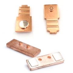
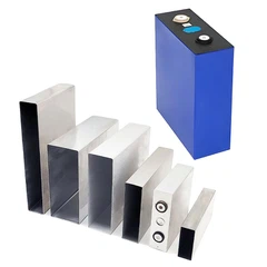
The rapid expansion of the new energy industry is redefining the technical thresholds for electrical interconnect components. As a critical structural element for the collection and distribution of high currents, the design of Laminated Busbars for Photovoltaic Inverters has evolved from a singular focus on conductivity into a comprehensive systems engineering discipline-integrating low inductance, high insulation integrity, and robust weather resistance. The Laminated Busbar for Electric Vehicle Power Distribution serves as a prime example of this trend; it must not only facilitate the series and parallel interconnection of individual battery cells within the battery pack but also maintain stable performance for decades while enduring the combined stresses of vibration, temperature fluctuations, and electrochemical corrosion. Fundamentally, understanding these technical requirements entails grasping the systemic constraints that new energy electrical architectures impose upon their interconnect components.
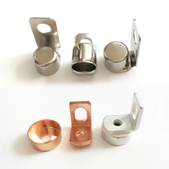
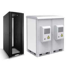
The specific application scenarios for composite laminated busbars dictate divergent technical approaches. Based on operating conditions, these applications can be categorized into four types: Rail Transit-where core requirements prioritize vibration resistance, flame retardancy, and broad temperature adaptability (necessitating compliance with flame retardancy standards such as EN 45545-2 HL2 or higher); Wind, Solar, and Energy Storage Systems-which must withstand outdoor environments characterized by high humidity, heat, and salt spray, and are designed for a service life of no less than 25 years; Power and Electrical Engineering-where the primary objective is high current-carrying capacity with minimal power loss, making insulation strength the paramount performance metric; and Industrial Control Systems-which emphasize compactness and resistance to electromagnetic interference (EMI). Furthermore, busbars are classified by conductor material into Copper (Type T) and Aluminum (Type L), and by temperature resistance rating into Class I (-40°C to 105°C) and Class II (-40°C to 130°C). Given the distinct requirements of each scenario, the selection of materials, insulation grades, and testing standards varies significantly; consequently, no single "universal" solution exists that can effectively serve all applications.

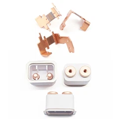
The core of the electrical design for Laminated Busbars intended for high-current power electronics is low inductance. Parasitic inductance must be controlled to within 100 nH; this is achieved by arranging the positive and negative conductor layers in a stacked configuration, utilizing the magnetic field cancellation effect of opposing currents to reduce overall inductance. Furthermore, where conductor layers overlap, corners must be rounded to prevent electric field concentration that could lead to partial discharge. Insulation resistance is tested in accordance with GB/T 24343; dielectric withstand voltage references GB/T 16935.1; partial discharge is measured per GB/T 7354; and temperature rise tests are conducted by applying the rated current and monitoring the temperature rise as specified in GB/T 21413.1. These are not optional checks, but mandatory inspection items for every shipped batch.
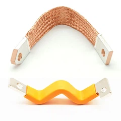
Environmental adaptability serves as the critical differentiator for products tailored to specific application scenarios. Laminated Busbars for Rail Transport applications must pass vibration and shock tests (GB/T 21563) as well as 21 cycles of cyclic damp heat testing. Products for Wind, Solar, and Energy Storage (WSES) and Industrial Control sectors require completion of 6 cycles of cyclic damp heat and 10 cycles of temperature variation. Conversely, products for Power and Electrical Engineering applications must withstand 21 cycles of cyclic damp heat combined with 100 cycles of temperature variation. Operating humidity is specified at ≤95% (non-condensing), while storage humidity ranges from 30% to 80%.
The differences in testing protocols for Composite Laminated Busbars across various scenarios are not merely a matter of complexity, but of necessity-the requirement for 21 damp heat cycles in rail transport applications, versus 100 temperature variation cycles in power engineering, reflects two fundamentally distinct failure mechanisms: vibration fatigue versus thermal expansion and contraction.
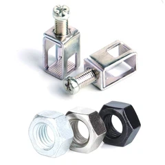
Safety and service life requirements constitute the rigid boundaries of the design. Overall flame retardancy must meet or exceed the UL94 V-0 standard, and compliance with the RoHS 2.0 environmental standard-prohibiting the use of hazardous substances-is mandatory. Products for Rail Transport and Power Engineering applications are designed for a service life of ≥30 years, while those for WSES and Industrial Control sectors are designed for ≥25 years. Fasteners are constructed from either carbon steel or stainless steel; specified tightening torques range from 1.3 N·m for M3 bolts up to 88.0 N·m for M12 bolts. Insufficient torque leads to increased contact resistance, whereas excessive torque causes thread stripping in the hole walls-both being common causes of field failures.
The manufacturing precision of Laminated Shunts and Busbars directly impacts their electrical consistency. The tolerance for hole center distances is ±0.5 mm. Unspecified linear tolerances adhere to Grade C of GB/T 1804-2018, while straightness and flatness conform to Grade K of GB/T 1184. The deviation in net weight is controlled within ±5%. Visual inspections are conducted under natural light from a distance of 350 cm; the insulation layer must be free of damage, delamination, or bubbles; conductor terminals must show no signs of oxidation or burrs; and fasteners must be securely fastened. These requirements-seemingly fundamental in nature-are, in fact, precisely the most challenging aspects to consistently stabilize during mass production.

In the manufacturing of BusBars for Active Power Filters (APF), the most easily underestimated aspect is neither the materials nor the tooling, but rather the lamination process between the insulation layer and the conductor. Micro-bubbles resulting from insufficient leveling of the adhesive layer can expand during prolonged thermal cycling, creating channels that ultimately lead to insulation failure-a defect that is extremely difficult to detect during final visual inspections. With the widespread adoption of 800V high-voltage platforms and ultra-fast charging technologies, BusBars for Transformers will face increasingly stringent requirements regarding parasitic inductance, temperature rise control, and insulation margins; consequently, intelligent inspection and digital traceability are rapidly becoming standard features.
If you are currently selecting BusBars for Electric Welding Machines for use in battery packs, inverters, or rail transit projects-or if you have concerns regarding the environmental adaptability test data of your existing solutions-we invite you to submit your operational parameters and technical drawings. Our application engineering team will provide structural recommendations within 48 hours.
contact us

Send Inquiry