



AgZnO vs. AgSnO2 Contacts in AC-3 and AC-4 Motor Starters: High Inrush Current Endurance
Oct 24, 2026
Leave a message
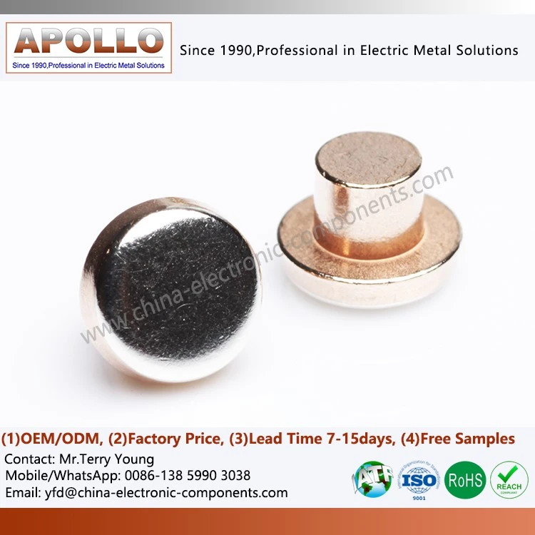
AgZnO (silver–zinc oxide) and AgSnO₂ (silver–tin oxide) are silver-based contact materials designed to balance electrical conductivity, arc-erosion resistance, and resistance to contact welding. In AC-3 motor starting, contacts typically make under starting current and break under running current; AC-4 inching and plugging impose more severe switching duty because contacts may make and break at high current more frequently. Material selection must therefore be based on the actual motor load, switching frequency, electrical endurance target, and contactor design-not oxide chemistry alone.
AC-3 and AC-4 Switching Duty: Motor Inrush Current and Arc Erosion
Why 6–8× rated current changes contact behavior
When an induction motor starts directly across the line, its initial current can reach approximately 6–8 times rated current, depending on motor design, supply conditions, and starting method. This is a common engineering estimate, not a universal value for every motor. The contact system must carry the transient current while maintaining adequate contact pressure and controlling local heating.
The primary electrical and mechanical stresses include:
High-current making: Contact closure may produce bounce and localized micro-arcs. Current concentration at microscopic asperities can cause local melting and material transfer.
Inductive current interruption: When contacts separate while current is flowing, stored energy in the motor circuit contributes to arc formation. Arc duration and energy depend on the circuit inductance, current, contact opening speed, and switching phase.
Contact welding: Localized melting can form a metallic bridge between opposing contact faces. If the bridge does not rupture normally during opening, contact separation can be delayed or prevented.
Material transfer and erosion: Repeated arcs redistribute contact material between the anode and cathode and can eject molten droplets. Contact geometry, polarity, arc motion, and material composition affect the net loss.
Thermal accumulation: High switching frequency can prevent the contact assembly from returning to thermal equilibrium between operations, increasing the risk of accelerated degradation.
At six times rated current, instantaneous resistive heating in an unchanged resistance path is 36 times the heating at rated current; at eight times rated current, it is 64 times. These ratios apply to the same resistance and instantaneous comparison. They do not directly predict contact temperature because current duration, arc voltage, heat capacity, heat transfer, and contact resistance vary during a switching event.
AC-3 versus AC-4: duty classification and contact wear
IEC 60947-4-1 defines requirements for contactors and motor starters, including utilization categories. AC-3 generally covers starting squirrel-cage motors and switching them off after they have reached operating speed. AC-4 covers more demanding duties such as plugging and inching, in which contact making and breaking can occur under severe current conditions.
| Design consideration | AC-3 motor starter | AC-4 motor starter |
| Typical operation | Start the motor, then interrupt the running current | Inching, plugging, or frequent reversing under demanding current conditions |
| Making duty | Includes motor starting current | Can include high-current making during repeated operations |
| Breaking duty | Typically interrupts motor running current | May interrupt current before the motor reaches normal speed |
| Arc exposure | Depends on motor, circuit, and switching conditions | Often more severe due to repeated high-current switching |
| Contact material requirement | Balance conductivity, erosion resistance, and welding resistance | Greater emphasis on switching endurance under severe making and breaking conditions |
| Validation priority | Rated operational current, utilization category, and required electrical life | Duty-specific endurance testing, contact wear, welding tendency, and temperature rise |
The utilization category is only one part of the rating. Rated operational voltage, operational current, short-circuit coordination, switching frequency and the manufacturer's declared electrical endurance must also match the application.
Arc energy and contact erosion mechanisms
Contact erosion is affected by several interacting variables:
1. Arc duration: Longer arc duration can increase the energy available for melting, evaporation, and droplet ejection.
2. Arc-root movement: Localized arc attachment can produce uneven craters and concentrated thermal damage.
3. Contact separation speed: Opening dynamics influence arc initiation, arc voltage, and the time available for material transfer.
4. Contact geometry: Contact diameter, thickness, curvature, and mounting position influence current distribution and arc movement.
5. Circuit conditions: Motor power factor, supply voltage, current phase, switching frequency and transient suppression affect arc behavior.
Silver-based oxide contacts are not immune to erosion. Their purpose is to control the balance between electrical conductivity, arc resistance, welding tendency, and material loss under a defined duty cycle.
AgZnO vs. AgSnO2: Oxide Chemistry, Arc Response and Welding Resistance
Silver–zinc oxide and silver–tin oxide material structures
AgZnO and AgSnO₂ are composite contact materials in which a conductive silver matrix contains a dispersed oxide phase. The silver matrix carries most of the electrical current, while the oxide distribution affects hardness, resistance to welding, arc response, and material transfer.
The behavior of a finished contact depends on more than its nominal chemical designation. Oxide fraction, particle size, distribution uniformity, porosity, silver-matrix continuity, processing history and contact geometry all influence performance.
AgSnO₂ is widely used in switching applications requiring resistance to contact welding and arc erosion. AgZnO may be considered for selected applications where its arc response, contact resistance, and wear behavior meet the specified operating conditions. Neither material should be assumed to outperform the other across all AC-3 and AC-4 applications without comparative test data.
Comparing arc response and surface-film behavior
| Engineering factor | AgZnO (silver–zinc oxide) | AgSnO₂ (silver–tin oxide) |
| Conductive matrix | Silver provides the primary conductive path | Silver provides the primary conductive path |
| Dispersed oxide phase | Zinc oxide | Tin dioxide |
| Arc response | Depends on oxide content, distribution, contact geometry, and arc conditions | Depends on oxide content, distribution, contact geometry, and arc conditions |
| Welding resistance | Must be evaluated against the specified making current, contact force, and circuit conditions | Commonly selected for demanding switching duties where welding resistance is important; actual performance remains design-dependent |
| Surface oxidation | Surface composition and contact resistance can change during switching | Oxide-rich surface regions can influence contact resistance and material transfer |
| Electrical endurance | Requires testing under the intended utilization category and duty cycle | Requires testing under the intended utilization category and duty cycle |
| Preferred selection method | Comparative endurance and contact-resistance data from the intended application | Comparative endurance and contact-resistance data from the intended application |
The phrase "oxide decomposition absorbs heat" should not be treated as a complete explanation of AgZnO performance. Zinc oxide is a stable oxide under many contact-operating conditions, and the actual thermal behavior depends on the local temperature, atmosphere, reaction pathway and microstructure. Similarly, AgSnO₂ performance cannot be reduced to a single "high-resistance oxide film" mechanism. Arc-driven surface changes, oxide redistribution, molten-metal movement and contact pressure interact during switching.
For material selection, the useful evidence is measured performance: contact resistance, welding tendency, erosion rate, temperature rise and electrical endurance under controlled conditions.
Why oxide dispersion matters more than nominal composition alone
A contact material with the correct nominal oxide fraction can still show inconsistent switching performance if the oxide phase is clustered or distributed unevenly. Large oxide agglomerates and pores can interrupt silver-matrix continuity, create local current-density variations and produce uneven arc erosion.
Key microstructural controls include:
Oxide particle distribution: A reasonably uniform dispersion helps reduce localized variation in the conductive matrix and wear behavior.
Silver-matrix continuity: The conductive phase must maintain an effective current path through the contact volume.
Porosity control: Excessive porosity reduces effective conducting area and can create local heating or mechanical weakness.
Density consistency: Density variation can indicate inconsistent consolidation or material flow and should be controlled against the approved material specification.
Interfacial integrity: Poor bonding between the silver matrix and oxide particles can contribute to local material loss under repeated arc exposure.
Request Material Evaluation & OEM Quote
Selecting AgZnO for Frequent Switching: AC-3, AC-4 and Inching Applications
Match contact material to the actual switching profile
AgZnO should be selected when comparative qualification data demonstrates that it meets the application's electrical endurance, contact-resistance, temperature-rise, and welding-resistance requirements. Frequent switching alone is not sufficient justification: the current waveform, contactor mechanism, circuit power factor and cooling conditions determine the severity of the duty.
| Application condition | Main contact risk | Material-selection criterion |
| AC-3 motor starting | Making-current stress followed by interruption of running current | Electrical endurance and acceptable contact wear at the specified operational current |
| AC-4 inching | Repeated switching before the motor reaches steady speed | Resistance to cumulative arc erosion and contact welding |
| Plugging or rapid reversing | Severe interruption and remaking under demanding current conditions | Tested endurance under the actual reversing sequence and duty cycle |
| High switching frequency | Heat accumulation and accelerated contact wear | Temperature-rise stability and endurance at the specified operations per hour |
| High contact force or restricted mechanism travel | Mechanical impact, deformation, and altered contact pressure | Material hardness, contact geometry, and mechanism-level validation |
| Compact contactor design | Localized heating and limited heat dissipation | Contact resistance, thermal performance and current-path geometry |
AgZnO and AgSnO₂ should be compared using contacts of equivalent dimensions, surface finish, mounting arrangement, and test conditions. Otherwise, a difference in observed wear may reflect geometry or contact force rather than material chemistry.
Electrical endurance test design under IEC 60947-4-1
An endurance test should reproduce the declared utilization category and relevant operating conditions. A material coupon test can provide useful screening data, but it cannot replace contactor-level qualification because the opening mechanism, arc chamber, magnetic blowout system, and contact pressure all affect switching performance.
A useful test plan defines:
Rated operational voltage and current, including the intended AC-3 or AC-4 duty.
Motor load characteristics, starting current and the actual make/break sequence.
Switching frequency, operating cycles and cooling intervals.
Contact force, opening speed and contact-gap requirements.
Initial and periodic contact-resistance measurements.
Contact wear, mass loss or dimensional recession where measurable.
Incidence of welding, failure to open, excessive bounce or unacceptable temperature rise.
Final inspection criteria and the required number of test samples.
IEC 60947-4-1 provides the relevant framework for contactors and motor starters. The applicable edition, product ratings, and customer acceptance requirements should be stated in the qualification plan. There is no universal number of electrical operations that establishes suitability for every AC-3 or AC-4 contactor.
Measuring erosion and resistance drift
A repeatable evaluation should distinguish contact-material wear from electrical degradation. Surface erosion can change the contact profile and reduce the remaining contact thickness; oxidation, transferred material and altered contact pressure can increase resistance even before the contact reaches its dimensional wear limit.
| Measurement | What it reveals | Important control |
| Contact resistance | Electrical stability of the closed contact | Standardized contact force, measurement current and connection points |
| Contact thickness or recession | Physical wear over the endurance sequence | Fixed datum and calibrated measurement method |
| Surface microscopy | Craters, transferred material, cracking and localized damage | Consistent magnification, lighting and image-analysis method |
| Temperature rise | Thermal behavior under current load | Defined ambient conditions, stabilization time and sensor position |
| Welding events | Failure to separate or excessive separation force | Recorded switching sequence and consistent failure criteria |
| Electrical endurance cycles | Operational durability under the specified duty | Controlled voltage, current, load and switching frequency |
A contact material should not be approved solely because its initial contact resistance is low. Initial resistance, resistance drift, wear and welding tendency must be assessed together over the required life cycle.
Powder Metallurgy, Extrusion and Cold Heading: Controlling AgZnO Microstructure
Powder preparation and oxide distribution
The electrical behavior of AgZnO contacts depends on the continuity of the silver matrix and the distribution of zinc oxide particles. Powder preparation and subsequent consolidation must control composition uniformity, particle dispersion, contamination, and porosity.
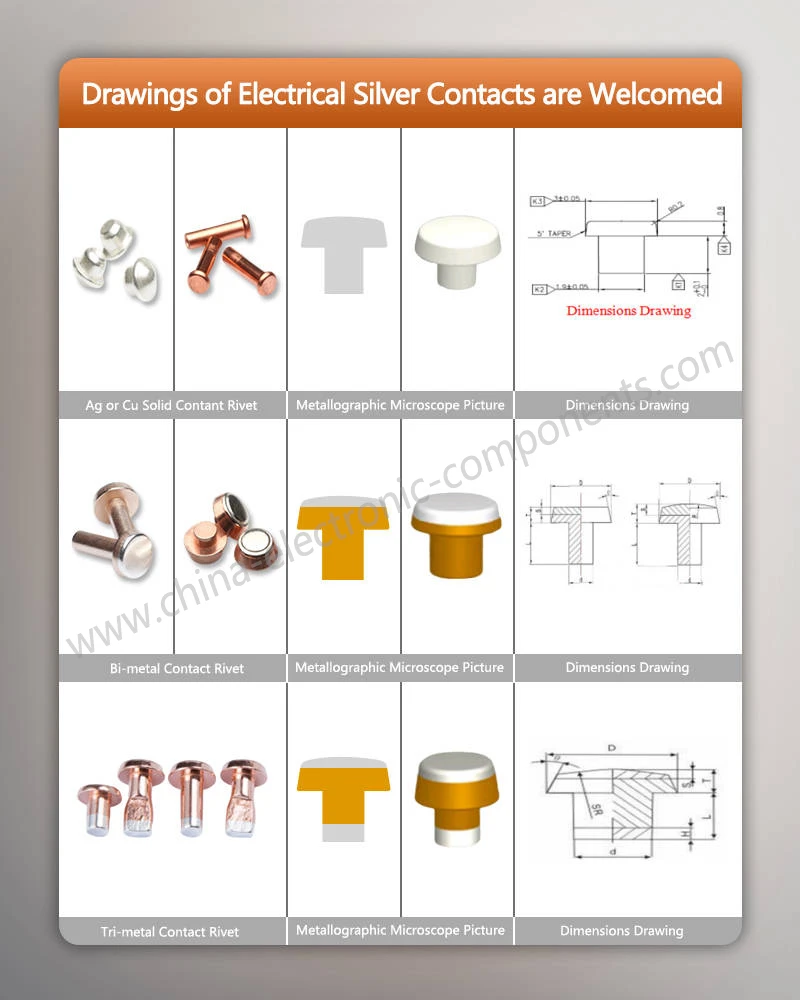
A representative manufacturing route may include powder preparation, blending or other qualified dispersion methods, consolidation, extrusion or other forming operations, blank preparation, cold heading where appropriate, and final sizing or finishing. The exact sequence depends on the contact geometry and the manufacturer's qualified process.
Important controls include:
Powder composition: Verify silver and oxide content against the approved material specification.
Mixing uniformity: Prevent localized oxide enrichment and segregation before consolidation.
Powder condition: Control particle-size distribution and contamination within the qualified process limits.
Consolidation: Establish parameters that achieve the required density and structural integrity.
Extrusion and forming: Control material flow, cracking, and dimensional consistency.
Final contact geometry: Maintain the specified diameter, thickness, flatness, and mounting features.
These operations should not be assumed to produce identical microstructures. Process parameters and material specifications must be validated for the actual AgZnO formulation.
Extrusion and cold heading: process selection
Extrusion and cold heading serve different manufacturing purposes. Extrusion can consolidate or shape material into a controlled cross-section, depending on the feedstock and process route. Cold heading forms a prepared blank through compressive deformation and can produce repeatable contact shapes at volume.
| Process | Main purpose | Primary process risks | Required controls |
| Powder blending or dispersion | Distribute oxide through the silver-based material | Segregation, agglomeration, and contamination | Composition checks and qualified mixing controls |
| Consolidation | Form a coherent material body | Residual porosity and inadequate bonding | Density measurement and structural examination |
| Extrusion | Produce a controlled section or promote material consolidation where applicable | Cracking, flow variation and dimensional instability | Tool condition, process parameters and section inspection |
| Cold heading | Form contact geometry from a prepared blank | Laps, cracking, eccentricity and dimensional drift | Blank quality, die condition and dimensional inspection |
| Final sizing or finishing | Meet contact geometry and surface requirements | Excessive material removal, deformation, or surface damage | Defined dimensions, surface criteria and inspection frequency |
| Contact assembly | Integrate the contact into the switching component | Poor seating, inadequate retention, or inconsistent alignment | Assembly force, geometry, and retention checks |
The term molecular diffusion welding should only be used when the joining process and mechanism are specifically established. It is not a generic substitute for powder consolidation, extrusion, or cold heading. Similarly, in-die riveting may be appropriate for some contact assemblies, but its suitability depends on the contact structure, substrate and retention requirements.
Microstructure and dimensional inspection
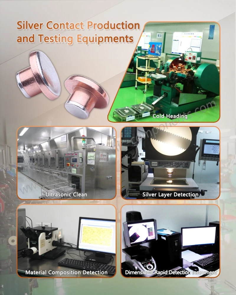
Metallographic examination can identify oxide agglomerates, porosity, cracking, and other microstructural conditions that may contribute to inconsistent performance. Optical microscopy is suitable for many routine examinations; higher-resolution methods may be needed when the feature size or suspected defect requires them.
Dimensional inspection should cover both the contact material and the finished component. A coordinate measuring machine (CMM) may be appropriate for complex geometries, while calibrated gauges or optical systems can be more efficient for high-volume features.
The inspection plan should define:
Sample location and orientation for metallographic sections.
Magnification and image-analysis rules.
Density and composition acceptance criteria.
Permitted dimensional variation and surface defects.
Measurement-system repeatability for critical dimensions.
Lot identification and traceability from material batch to finished contacts.
Linking process control to electrical performance
Microstructure and dimensional variation should be linked to functional test results rather than managed as isolated inspection items. For example, a change in oxide dispersion may affect arc behavior, while a change in contact thickness can alter heat dissipation and the amount of material available for wear.
A process-validation matrix should connect each critical characteristic to its potential failure mode, inspection method, and reaction plan.
| Critical characteristic | Potential functional impact | Verification method |
| Oxide fraction and distribution | Changes in arc response, conductivity and wear | Material analysis and metallographic examination |
| Density and porosity | Reduced effective conductive area and local heating | Density measurement and section inspection |
| Contact dimensions | Changes in contact force, current density and wear allowance | Calibrated dimensional inspection |
| Surface condition | Unstable initial contact and localized arc attachment | Defined visual or microscopic criteria |
| Contact retention | Movement or separation during switching | Retention testing and assembly inspection |
| Finished-contact resistance | Additional voltage drop and heat generation | Electrical measurement under specified conditions |
Request Material Evaluation & OEM Quote
OEM AgZnO Electrical Contact Supply: Qualification and Production Release
Engineering data required for material selection
Before approving AgZnO or AgSnO₂ for a motor starter, the engineering team should define the operating envelope and the acceptance criteria. A supplier quotation based only on contact diameter and nominal material designation is insufficient for applications with demanding AC-4 switching requirements.
The technical package should identify:
Contact drawing, dimensions, tolerances, and mounting configuration.
Material designation, oxide content, and applicable material specification.
Contactor model, rated operational voltage and current.
Intended utilization category under IEC 60947-4-1.
Motor starting, inching, or reversing duty and switching frequency.
Required electrical endurance and allowable contact wear.
Contact-resistance and temperature-rise limits.
Required material analysis, dimensional reports, and qualification samples.
Annual demand, forecast, tooling expectations, and change-control requirements.
Where the contact material is being changed in an existing contactor, the evaluation should also consider compatibility with the contact carrier, contact force, arc chamber, and switching mechanism. A material substitution is not automatically a drop-in replacement simply because the nominal dimensions match.
Production quality records and change control
For a qualified production program, the supplier and customer should agree on which material and process characteristics require formal approval. Depending on the program, records may include material certificates, dimensional inspection results, microstructure evaluations, endurance test reports, and traceability documentation.
Any change to oxide formulation, powder preparation, forming route, tooling, finishing or approved manufacturing location should be evaluated against the agreed change-control process. Requalification requirements depend on the customer's quality requirements and the effect of the change on product performance.
Apollo Electronic Components (Xiamen) Co., Ltd can evaluate drawings and technical requirements for silver electrical contacts and contact assemblies, with the manufacturing and validation scope defined for each project. Specific claims about AgZnO composition, production capacity, electrical endurance, or certification should be supported by applicable product and facility records.
FAQ: AgZnO and AgSnO₂ Motor Starter Contacts
Is AgZnO better than AgSnO₂ for AC-4 motor starters?
Not universally. The correct choice depends on switching current, circuit conditions, contactor geometry, contact force, and required electrical endurance. Compare both materials under the same AC-4 test conditions before approving a substitution.
How should AC-3 contactor contact erosion be evaluated?
Measure contact resistance, physical wear, and temperature rise during a defined endurance test. Record the voltage, current, switching sequence, and operating frequency, and assess welding or failure-to-open events against the agreed acceptance criteria.
What manufacturing controls matter most when sourcing AgZnO electrical contacts?
Control oxide composition and dispersion, density, porosity, contact dimensions, and surface condition. Validate these characteristics through material analysis, metallography, dimensional inspection, and application-specific electrical endurance testing.
contact us
Send Inquiry